Select Phase System to See Voltage
Select a load input type above
Fill in the required inputs below to instantly generate breaker size, conductor size, EGC size, raceway size and maximum circuit length.
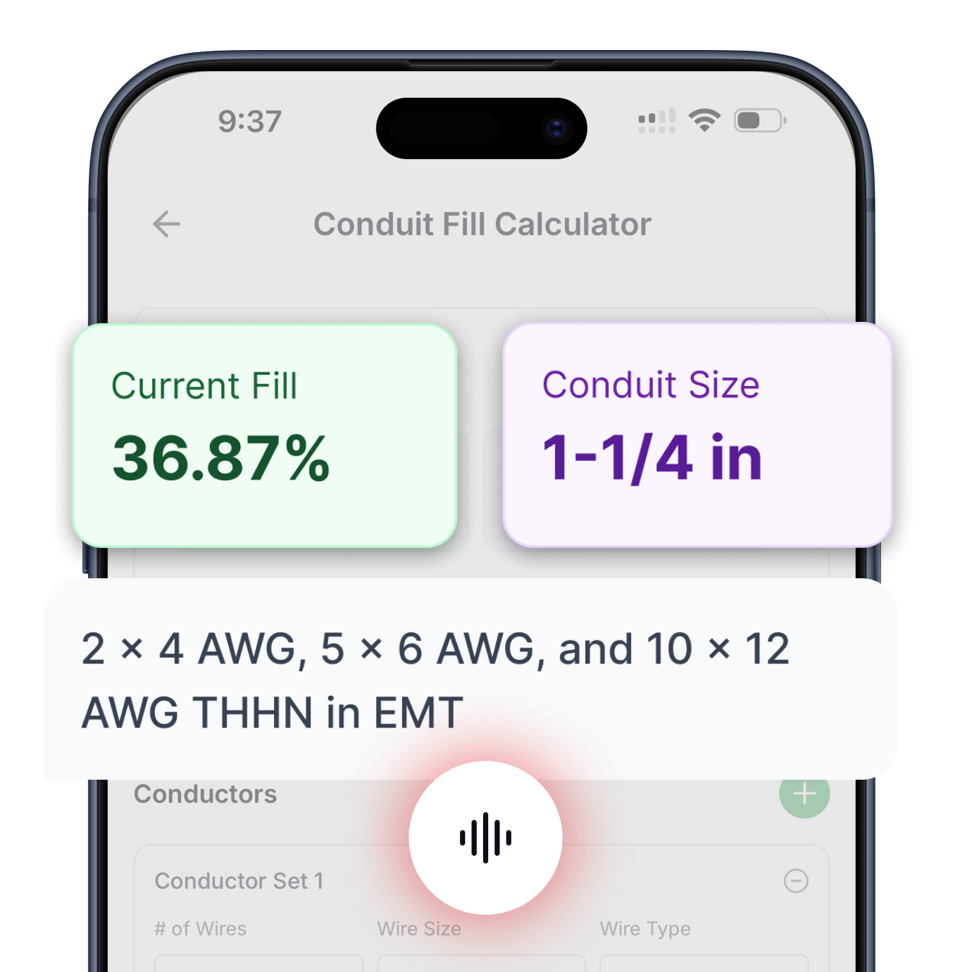
Enter the conductor details and select a conduit type to calculate fill percentage and required conduit size.
Select Phase System to See Voltage
Fill in the required inputs below to instantly generate protection size, conductor size, EGC size, raceway size and maximum circuit length.
No items added
No items added
No items added
No items added
No items added
No items added
No items added
Enter the square footage of the building to calculate the required electrical service size based on building load.
Fill in the required inputs below to instantly generate protection size, conductor size, EGC size, raceway size and maximum circuit length.
Select Phase System to See Voltage
Fill in the required inputs below to instantly generate protection size, conductor size, EGC size, raceway size and maximum circuit length.
Select Primary Voltage to See Secondary Options
Fill in the required inputs below to instantly generate protection, conductor, EGC, bonding jumper, and raceway sizes for both primary and secondary sides.
Select Phase to See Voltage
Fill in the required inputs below to calculate the voltage drop across your circuit based on conductor size, load, and cable length.
Select Phase to See Voltage
Fill in the required inputs below to calculate the maximum circuit distance allowed before voltage drop exceeds your limit.
Select Phase to See Voltage
Fill in the required inputs below to calculate the minimum conductor size needed to stay within your voltage drop limit.
Select Phase System to See Voltage
Select a load input type above
Fill in the required inputs below to instantly generate breaker size, conductor size, EGC size, raceway size and maximum circuit length.
Enter the conductor details and select a conduit type to calculate fill percentage and required conduit size.
Select Phase System to See Voltage
Fill in the required inputs below to instantly generate protection size, conductor size, EGC size, raceway size and maximum circuit length.
No items added
No items added
No items added
No items added
No items added
No items added
No items added
Enter the square footage of the building to calculate the required electrical service size based on building load.
Fill in the required inputs below to instantly generate protection size, conductor size, EGC size, raceway size and maximum circuit length.
Select Phase System to See Voltage
Fill in the required inputs below to instantly generate protection size, conductor size, EGC size, raceway size and maximum circuit length.
Select Primary Voltage to See Secondary Options
Fill in the required inputs below to instantly generate protection, conductor, EGC, bonding jumper, and raceway sizes for both primary and secondary sides.
Select Phase to See Voltage
Fill in the required inputs below to calculate the voltage drop across your circuit based on conductor size, load, and cable length.
Select Phase to See Voltage
Fill in the required inputs below to calculate the maximum circuit distance allowed before voltage drop exceeds your limit.
Select Phase to See Voltage
Fill in the required inputs below to calculate the minimum conductor size needed to stay within your voltage drop limit.
The maximum circuit length calculator determines how far electrical conductors can extend from the power source to the load while maintaining acceptable voltage drop. This calculation reverses the typical voltage drop analysis by working backward from a voltage drop limit to find the maximum allowable distance. Understanding maximum circuit length helps designers plan electrical layouts, position equipment optimally, and select appropriate conductor sizes during the design phase.
Circuit length limitations arise from conductor resistance creating voltage drop proportional to current and distance. Every foot of conductor adds resistance that converts some electrical energy to heat, reducing voltage available at the load. The maximum circuit length represents the distance where voltage drop reaches the acceptable limit, beyond which either larger conductors or circuit modifications are needed.
The NEC recommends limiting voltage drop to 3% for branch circuits and 2.5% for feeders, with combined feeder and branch circuit drop not exceeding 5%. These recommendations ensure equipment receives adequate voltage for proper operation and efficiency. The maximum circuit length calculation uses these percentages as constraints, determining the longest circuit that stays within limits for given conductor size and current.
This calculator proves invaluable during design when equipment locations are flexible or when evaluating whether existing conductor sizes can serve new equipment locations. Rather than calculating voltage drop for a specific length and finding it excessive, the calculator reveals the maximum distance possible with selected conductors, allowing informed decisions about equipment placement or conductor upsizing.
Maximum circuit length is calculated by rearranging the voltage drop formula to solve for length rather than voltage drop. The basic relationship for single-phase circuits is: Maximum Length = (VD × 1000) ÷ (2 × R × I), where VD is allowable voltage drop in volts, R is conductor resistance in ohms per 1000 feet, and I is load current in amperes.
The allowable voltage drop in volts equals the system voltage multiplied by the maximum percentage. A 240-volt circuit with 3% maximum drop allows 7.2 volts of drop (240 × 0.03). This voltage value becomes the VD term in the maximum length formula. Converting percentage to actual voltage provides the concrete voltage budget available for conductor resistance losses.
The factor of 1000 in the numerator converts conductor resistance from ohms per 1000 feet to ohms per foot. Conductor resistance tables list values per 1000 feet, so this conversion factor allows calculating length in feet rather than thousands of feet. The multiplier matches the units of resistance tables to the desired output unit of feet.
The denominator contains the factor 2 for single-phase circuits accounting for current flow in both supply and return conductors, conductor resistance R from NEC tables, and load current I. These three factors determine how quickly voltage drop accumulates per foot of circuit length. Higher current or resistance increases voltage drop per foot, reducing maximum allowable circuit length.
Single-phase circuits use the multiplier 2 in the maximum length formula because current flows out through one conductor and returns through the other conductor. Both conductors contribute resistance and voltage drop, effectively doubling the resistance compared to a single wire. The formula Maximum Length = (VD × 1000) ÷ (2 × R × I) accounts for this two-conductor configuration.
A 240-volt single-phase circuit using 12 AWG copper conductors with 1.93 ohms per 1000 feet resistance and carrying 15 amperes allows 7.2 volts drop (3%). The maximum length calculates as: (7.2 × 1000) ÷ (2 × 1.93 × 15) = 124 feet. This represents the one-way distance from source to load, beyond which voltage drop exceeds 3%.
The calculated maximum length provides a hard limit for the given conditions. Running this circuit 125 feet would create 3.024% voltage drop, exceeding the 3% recommendation. Running it 150 feet would create 3.629% drop, well over the limit. These small distances beyond the maximum quickly accumulate unacceptable voltage drop.
Single-phase 120-volt circuits have particularly restrictive maximum lengths because the allowed voltage drop in volts is half that of 240-volt circuits for the same percentage. A 120-volt circuit with 3% limit allows only 3.6 volts of drop compared to 7.2 volts for 240 volts. This tighter voltage budget in volts means 120-volt circuits reach voltage drop limits at half the distance of 240-volt circuits with the same conductor size and current.
Three-phase circuits use a multiplier of 1.73 (square root of 3) instead of 2 in the maximum length formula, reflecting the more efficient voltage drop characteristics of three-phase systems. The formula becomes: Maximum Length = (VD × 1000) ÷ (1.73 × R × I). The lower multiplier means three-phase circuits can extend significantly farther than single-phase circuits with the same conductor size and current.
A 480-volt three-phase circuit using 10 AWG copper conductors with 1.21 ohms per 1000 feet resistance and carrying 20 amperes allows 14.4 volts drop (3%). The maximum length calculates as: (14.4 × 1000) ÷ (1.73 × 1.21 × 20) = 343 feet. This distance is substantially longer than a comparable single-phase circuit could achieve.
The three-phase advantage comes from distributing current across three conductors rather than concentrating it in two conductors. While each conductor still has the same resistance, the geometric relationship between line-to-line voltage and phase current creates the 1.73 factor rather than 2. This difference allows approximately 15% longer circuit runs for three-phase compared to single-phase at equivalent voltage drop.
Three-phase systems also benefit from higher typical voltages. Industrial facilities commonly use 480-volt three-phase, providing 14.4 volts allowable drop at 3% compared to 7.2 volts for 240-volt single-phase. The combination of higher voltage and more efficient three-phase distribution allows much longer circuit runs, explaining why industrial facilities can locate equipment farther from electrical panels than residential installations.
Conductor size dramatically affects maximum circuit length because resistance decreases substantially as conductor size increases. Each step up in conductor size (decrease in AWG number) reduces resistance by approximately 20-25%, allowing proportionally longer circuit runs. This relationship makes conductor upsizing an effective strategy for extending circuit reach.
A circuit using 12 AWG copper with 1.93 ohms per 1000 feet resistance can extend certain distance. Upgrading to 10 AWG copper with 1.21 ohms per 1000 feet increases maximum length by the ratio of resistances: the 10 AWG circuit extends approximately 60% farther than the 12 AWG circuit (1.93 ÷ 1.21 = 1.595). This substantial improvement often justifies the additional conductor cost.
Continuing to larger conductors provides diminishing returns for each size increase. Moving from 10 AWG to 8 AWG increases maximum length by about 55%. Moving from 8 AWG to 6 AWG adds another 40%. While each size increase helps, the percentage improvement decreases as conductors get larger because the resistance reduction per size step becomes smaller in absolute terms.
Very large conductors using kcmil sizing continue reducing resistance but at great cost. A 500 kcmil conductor has very low resistance allowing extremely long runs, but costs dramatically more than smaller conductors. Economic analysis balances conductor cost against the value of extended circuit reach or the cost of alternative solutions like sub-panels or voltage regulators.
Load current has an inverse relationship with maximum circuit length - doubling current halves maximum length. This relationship appears directly in the formula where current is in the denominator. Higher current creates more voltage drop per foot of conductor, reducing the distance that can be covered within voltage drop limits.
A circuit carrying 10 amperes can extend twice as far as the same circuit carrying 20 amperes, assuming identical voltage, conductor size, and voltage drop limits. If the 10-ampere circuit has maximum length of 200 feet, the 20-ampere circuit maxes out at 100 feet. This inverse relationship makes reducing load current an effective strategy for extending circuit reach.
Variable loads present a decision point for maximum length calculations. Equipment that alternates between 10 and 30 amperes should be evaluated at 30 amperes to ensure adequate voltage during peak load. Using average current might show acceptable circuit length, but actual voltage drop during peak periods would exceed limits, potentially causing equipment malfunction.
Continuous loads requiring 125% conductor sizing for ampacity still use actual operating current for maximum length calculations. A 20-ampere continuous load requires conductors rated for 25 amperes (20 × 1.25), but voltage drop calculations use the actual 20 amperes flowing through those oversized conductors. The larger conductors required for continuous load rating have lower resistance, providing better voltage drop performance than minimum-sized conductors.
The maximum voltage drop percentage directly determines allowable circuit length. More restrictive voltage drop limits reduce maximum circuit length proportionally. Changing from 3% to 2% voltage drop limit cuts maximum circuit length by one-third for the same conductors and current. This relationship shows how voltage drop standards significantly affect circuit design.
The standard 3% limit for branch circuits provides good equipment performance while allowing reasonable circuit lengths. Equipment operates reliably within this voltage range, and circuits can extend moderate distances without excessive conductor upsizing. Tightening to 2% improves voltage performance but requires 33% shorter circuits or larger conductors to maintain the same distance.
Some installations specify more stringent voltage drop limits than NEC recommendations. Critical equipment, precision machinery, or sensitive electronics may require 1-2% voltage drop for proper operation. These tighter limits substantially reduce maximum circuit length, often requiring sub-panels near load centers or significantly oversized conductors to deliver necessary voltage quality.
Feeder circuits use 2.5% or 5% voltage drop limits depending on whether branch circuits must also fit within the total voltage budget. A feeder using the full 5% limit doesn't leave room for branch circuit voltage drop, violating the combined 5% recommendation. Using 2.5% for feeders reserves 2.5% for branch circuits, maintaining total drop within recommendations.
Copper and aluminum conductors have different resistance values significantly affecting maximum circuit length. Copper's lower resistance allows longer circuit runs than aluminum of the same size. A 10 AWG copper conductor with 1.21 ohms per 1000 feet extends about 60% farther than 10 AWG aluminum with 1.99 ohms per 1000 feet for identical current and voltage drop limits.
The resistance difference between copper and aluminum means aluminum circuits need approximately two wire sizes larger than copper for equivalent voltage drop performance. A circuit using 10 AWG copper would need about 6 AWG aluminum to achieve similar maximum length. This sizing difference partly offsets aluminum's cost advantage, though aluminum still provides economic benefits for very large conductor sizes.
Aluminum's lower cost and weight make it attractive for large conductors and long runs despite requiring larger wire sizes. For conductors larger than 2/0 AWG, aluminum often costs less than copper even accounting for the larger size needed. The weight savings simplify installation and reduce structural support requirements for long conduit runs.
Material selection affects not just maximum length but also termination requirements and long-term reliability. Aluminum requires anti-oxidant compound at terminations and connectors rated for aluminum to prevent high-resistance connections. These requirements add installation complexity and cost that must be weighed against material savings when choosing between copper and aluminum.
Conductor resistance varies with temperature, affecting maximum circuit length calculations. Standard NEC resistance values assume 75°C conductor temperature, representing loaded conductors in typical conditions. Conductors operating at different temperatures have proportionally different resistance affecting actual voltage drop and maximum circuit length.
Resistance increases approximately 0.4% per degree Celsius for copper conductors. A conductor operating at 90°C has roughly 6% higher resistance than the same conductor at 75°C [(90-75) × 0.4% = 6%]. This increased resistance reduces maximum circuit length by about 6% compared to calculations using 75°C resistance values. The difference is modest but measurable in critical applications.
Conductors in hot environments experience elevated temperature increasing their resistance beyond table values. Attic installations in hot climates or conductors exposed to direct sunlight may operate at temperatures well above 75°C. These installations experience more voltage drop than standard calculations predict, effectively reducing maximum circuit length.
Cold environments reduce conductor resistance below table values, slightly increasing maximum circuit length. Underground conductors or installations in climate-controlled spaces may operate cooler than 75°C, experiencing less resistance and voltage drop than calculations predict. However, standard calculations using 75°C values remain appropriate for most design work, providing conservative results.
AC circuits experience skin effect where current concentrates near conductor surface at higher frequencies, effectively reducing conductor cross-sectional area available for current flow. This phenomenon increases AC resistance above DC resistance, particularly for larger conductor sizes. Maximum length calculations should account for this difference when accuracy is critical.
NEC Chapter 9, Table 8 provides DC resistance values suitable for most residential and light commercial calculations. Table 9 provides AC resistance values accounting for skin effect and proximity effect from adjacent conductors. For conductors smaller than 1/0 AWG, the difference between DC and AC resistance is minimal, making DC values acceptable for maximum length calculations.
Larger conductors show significant differences between DC and AC resistance. A 500 kcmil conductor might have 10-15% higher AC resistance than DC resistance due to skin effect. Using DC resistance values for large conductor calculations overestimates maximum circuit length. For conductors 1/0 AWG and larger, consider using AC resistance values for more accurate predictions.
True DC circuits use DC resistance values directly without concern for skin effect. Battery systems, solar installations, and DC motor circuits use Table 8 resistance values exclusively. These installations experience voltage drop based purely on DC resistance without AC phenomena affecting performance.
Power factor affects voltage drop in AC circuits, though the impact is often neglected in simplified calculations. When loads have power factor less than unity, the voltage drop includes both resistive and reactive components. The calculator can account for power factor when specified, providing more accurate maximum length for inductive loads.
Unity power factor (1.0) represents purely resistive loads where voltage and current are in phase. Resistive loads like heating elements and incandescent lighting have power factor near 1.0. For these loads, simplified calculations using only conductor resistance provide accurate maximum length predictions.
Inductive loads including motors, transformers, and fluorescent lighting have power factors typically ranging from 0.7 to 0.9. These loads create reactive current that affects voltage drop beyond simple resistance calculations. A default power factor of 0.85 represents typical mixed loads in commercial and industrial facilities, providing reasonable accuracy without detailed load analysis.
Correcting power factor through capacitor installation reduces current for a given real power load, effectively increasing maximum circuit length. Power factor correction capacitors supply reactive current locally, reducing current drawn from the source. This current reduction allows longer circuit runs or smaller conductors for the same voltage drop percentage.
Branch circuits connect final loads to panelboards and typically use the 3% voltage drop limit. The maximum circuit length calculation using 3% determines how far branch circuits can extend from panels to outlets, lights, or equipment. This limit ensures adequate voltage reaches equipment for proper operation and efficiency.
Feeder circuits carry power from service equipment to distribution panels or sub-panels and use 2.5% voltage drop limit when branch circuits will also incur drop. Calculating maximum feeder length with 2.5% limit ensures combined feeder and branch circuit drop stays within the 5% total recommendation. This coordination requires considering both feeder and branch circuit lengths in complete distribution system design.
Feeders serving only fixed equipment without additional branch circuits can use up to 5% voltage drop because no downstream circuits add additional drop. A feeder running to a single motor or piece of equipment represents the complete circuit from source to load. Using the full 5% allowance provides maximum circuit length for these direct-connection scenarios.
Sub-panel locations should consider both feeder length from main panel and typical branch circuit lengths from sub-panel to loads. Positioning sub-panels to minimize total circuit length optimizes voltage drop performance. A central sub-panel location with moderate feeder length and short branch circuits often performs better than locating the sub-panel at one extreme requiring long branch circuits to reach distant loads.
Maximum circuit length calculations guide equipment placement during facility design. Knowing that specific conductor sizes can extend certain distances from electrical panels helps position equipment optimally. Equipment requiring large conductors or having strict voltage requirements should be located near panels, while less demanding loads can be positioned farther away.
Motor loads particularly benefit from maximum length analysis because motors are sensitive to voltage drop affecting starting torque and operating temperature. Positioning large motors within maximum circuit length for reasonable conductor sizes avoids expensive conductor upsizing. When motor location is flexible, placing motors within 150-200 feet of panels allows standard conductor sizing.
Kitchen equipment in commercial facilities often concentrates high-current loads in one area. Planning electrical panel locations to minimize circuit length to kitchen areas reduces conductor costs and improves voltage performance. Alternatively, installing a sub-panel in or near the kitchen provides short branch circuits to equipment even if the feeder to the sub-panel is long.
Outdoor lighting circuits can extend considerable distances from buildings to parking areas, pathways, or landscape features. Maximum circuit length calculations determine whether branch circuits can reach distant fixtures or whether intermediate junction boxes with local overcurrent protection are needed. Higher voltage (277V vs 120V) dramatically extends outdoor lighting circuit reach.
When required circuit length exceeds maximum calculated length, two primary solutions exist: install larger conductors or install a sub-panel closer to loads. Economic analysis comparing these options identifies the most cost-effective approach. Larger conductors cost more per foot but require no additional equipment, while sub-panels add equipment cost but allow using smaller branch circuit conductors.
Conductor upsizing makes economic sense for single circuits or when the required increase is modest. Increasing from 12 AWG to 10 AWG adds perhaps $0.50 per foot, totaling $100 for a 200-foot circuit. This modest investment extends maximum circuit length by 60% and may be cheaper than sub-panel installation costing $500-1000 for panel, breakers, and installation labor.
Sub-panels become economical when serving multiple circuits that would all require upsizing. Installing a sub-panel with $800 cost and running four branch circuits at standard sizes often costs less than upsizing four long circuits. The sub-panel also provides flexibility for future circuit additions and reduces total conductor quantity needed throughout the facility.
Very long distances favor sub-panels because the required conductor upsizing becomes extreme. A circuit needing to extend 400 feet might require 4 AWG conductors where 12 AWG would suffice for 100 feet. The massive conductor cost for the long run exceeds sub-panel cost, making the sub-panel the economical choice while also improving voltage performance.
Circuits serving multiple loads at different distances require modified analysis. The maximum circuit length to the farthest load determines whether the circuit meets voltage drop limits. Intermediate loads closer to the source experience less voltage drop than the calculation predicts, but the farthest load governs circuit sizing.
Series circuits with multiple loads add complexity because current varies along the circuit length. A circuit serving three loads of 5, 10, and 8 amperes carries 23 amperes for the first portion, 18 amperes to the second load, and 8 amperes to the third load. Maximum length calculations must account for these varying currents along the circuit, with each section evaluated separately.
Radial circuits serving multiple loads from a common point simplify analysis because each branch is evaluated independently. A junction box with three circuits extending to different loads requires checking maximum length for each branch individually. Each branch starts at the junction box and extends to its load, with voltage drop accumulating from the source through the home run to the junction box, then through each branch.
At exactly the maximum calculated length, voltage drop equals the specified limit. Operating at this threshold provides no margin for variations in actual resistance, temperature, or current. Professional practice suggests designing for slightly less than maximum length, providing margin for real-world variations and ensuring reliable operation.
A circuit designed at 90% of maximum calculated length provides 10% margin for unforeseen factors. This margin accommodates measurement errors in circuit length, variations in conductor resistance from manufacturing tolerances, temperature effects, and minor load increases over time. The modest reduction in maximum length significantly improves reliability.
Circuits operated well below maximum length enjoy improved voltage performance and efficiency. Operating at 60-70% of maximum length provides excellent voltage at loads and substantial margin for variations. This conservative approach costs little in conductor sizing but ensures robust performance throughout the circuit's service life.
Measuring actual voltage drop in completed installations verifies design calculations. Measure voltage at the source and load simultaneously under full load to capture actual voltage drop. Comparing measured drop to calculated values identifies whether the installation performs as designed or whether problems exist requiring investigation.
Designing circuits with future load growth in mind affects maximum length calculations. Using anticipated future current rather than initial current provides circuit length that remains adequate as loads increase. This forward-looking approach prevents circuit modifications when equipment is upgraded or added.
Adding 20-25% to initial load current in maximum length calculations provides growth margin. A circuit initially carrying 20 amperes calculated using 25 amperes has maximum length that remains valid as loads increase to 25 amperes. This margin costs little in initial design but prevents future circuit capacity limitations.
Installing conductors larger than minimum required provides future capacity without circuit modifications. Using 8 AWG where 10 AWG meets current requirements allows longer maximum length and higher current capacity for future expansion. The additional conductor cost during initial installation is far less than replacing undersized conductors later.
Conductor routing affects actual circuit length beyond straight-line distance. Conduit follows walls, ceilings, and structural elements rather than taking direct paths. Actual conductor length typically exceeds straight-line distance by 25-40% accounting for vertical runs, horizontal routing, and obstacles. Maximum length calculations should use realistic conductor routing lengths.
Bundled circuits in the same conduit experience reduced heat dissipation requiring ampacity derating per NEC 310.15(C)(1). While this derating doesn't directly affect voltage drop calculations, it affects conductor sizing. Circuits requiring ampacity derating need larger conductors, which coincidentally improve voltage drop performance and increase maximum circuit length.
High ambient temperature locations require conductor ampacity correction factors from NEC 310.15(B)(2)(a), similar to bundling effects. These corrections require larger conductors for ampacity compliance, providing better voltage drop performance as a beneficial side effect. Hot environments also increase conductor resistance above table values, slightly reducing maximum circuit length.
Welding circuits present extreme voltage drop challenges due to very high currents during welding operation. Maximum circuit length for welding equipment is often severely limited, requiring large conductors or equipment location very near electrical panels. Some welding equipment includes internal compensation for voltage drop, but circuit sizing still requires meeting voltage requirements.
Electric vehicle charging circuits carry continuous high current for extended periods. Level 2 chargers drawing 30-40 amperes for several hours must maintain voltage within limits throughout charging sessions. Maximum circuit length calculations ensure adequate voltage throughout the charging cycle, preventing charger malfunction or reduced charging rate from low voltage.
Solar panel installations involve DC circuits where voltage drop affects system efficiency. Maximum circuit length from solar array to inverter must maintain adequate voltage to prevent system efficiency losses. DC voltage drop calculations use the same basic principles as AC circuits but without consideration for power factor or AC resistance effects.
While the NEC doesn't mandate voltage drop limits, maintaining circuits within recommended limits represents good engineering practice. Documentation showing maximum circuit length calculations demonstrates professional design and helps with permit approval. Some jurisdictions adopt mandatory voltage drop limits as amendments to the NEC, making these calculations code requirements.
Design drawings showing circuit lengths and conductor sizes should indicate voltage drop compliance. Noting calculated maximum lengths and actual circuit lengths on drawings helps installers verify proper routing and helps inspectors confirm code compliance. This documentation prevents field confusion about why certain circuits use larger conductors than ampacity alone would require.
Specifications for commercial and industrial projects often mandate specific voltage drop limits. Design specifications may require more stringent limits than NEC recommendations, such as 2% for branch circuits or 3% for feeders. Maximum circuit length calculations must use project-specific limits rather than general NEC recommendations when specifications are more restrictive.

Circuit Calculations
Size conductors, breakers, and raceways for any branch circuit or feeder. Includes automatic voltage drop calculations and equipment grounding conductor sizing.
Try Circuit Calculator ->

Load Calculator
Complete dwelling unit load calculations following NEC Article 220. Size service conductors and calculate demand loads for residential installations.
Try Load Calculator ->

Conduit Fill
Determine minimum conduit size based on conductor count and type. Supports all common conductor insulations and raceway types per NEC Chapter 9.
Try Conduit Calculator ->

Transformer Calculator
Complete primary and secondary sizing for single-phase and three-phase transformers. Includes protection, conductors, bonding jumpers, and raceways.
Try Transformer Calculator ->

Motor Calculator
Get proper breaker and fuse sizing for single-phase and three-phase motors from 1/6 HP to 10 HP. Includes conductor sizing and both breaker and fuse options.
Try Motor Calculator ->

Voltage Drop
Three specialized calculators: find minimum conductor size for a given length, calculate maximum circuit length for a conductor size, or determine actual voltage drop percentage.
Try Voltage Drop Calculator ->

Cooling & Heat Pump Calculator
Size circuits for air conditioning or heat pump equipment using nameplate MCA and MOCP values. Handles single-phase and three-phase systems.
Try Cooling & Heat Pump Calculator ->

Resistive Heating Calculator
Calculate circuits for electric heating equipment including baseboard heaters and unit heaters, based on nameplate ratings. Handles single-phase and three-phase systems.
Try Resistive Heating Calculator ->
Get instant, code-compliant answers with voice commands—no typing, no dropdowns, no hassle.