Select Phase System to See Voltage
Select a load input type above
Fill in the required inputs below to instantly generate breaker size, conductor size, EGC size, raceway size and maximum circuit length.
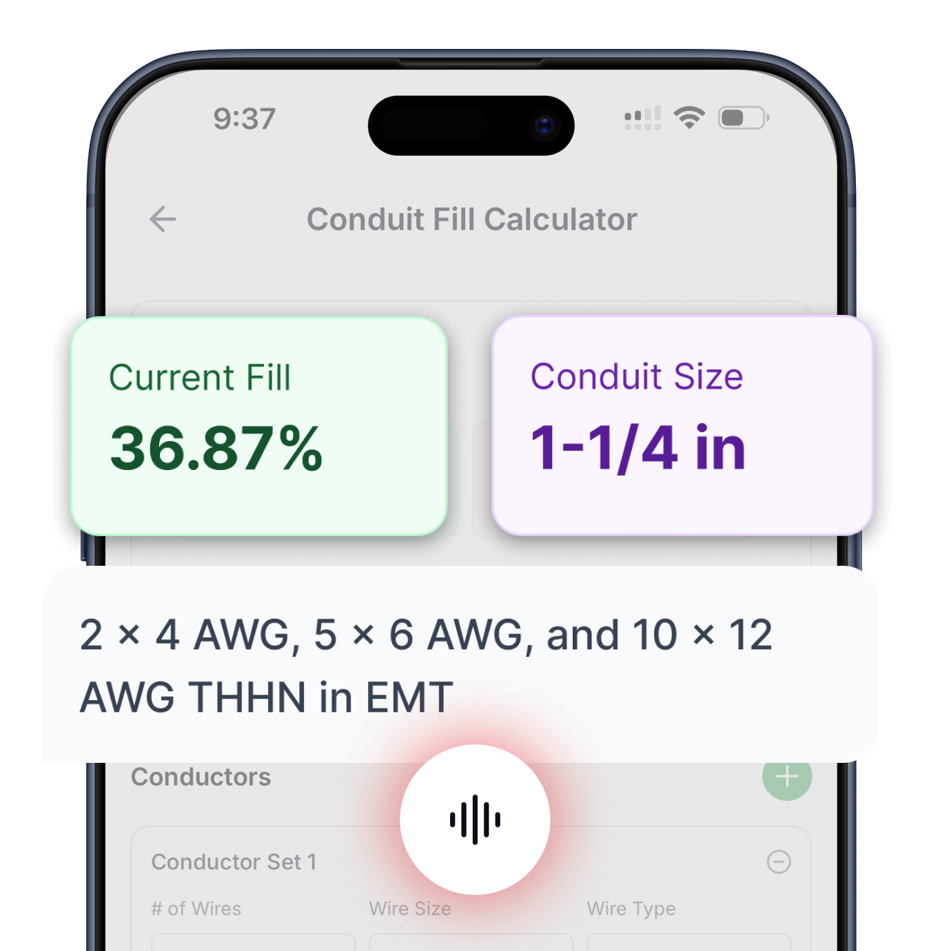
Enter the conductor details and select a conduit type to calculate fill percentage and required conduit size.
Select Phase System to See Voltage
Fill in the required inputs below to instantly generate protection size, conductor size, EGC size, raceway size and maximum circuit length.
No items added
No items added
No items added
No items added
No items added
No items added
No items added
Enter the square footage of the building to calculate the required electrical service size based on building load.
Fill in the required inputs below to instantly generate protection size, conductor size, EGC size, raceway size and maximum circuit length.
Select Phase System to See Voltage
Fill in the required inputs below to instantly generate protection size, conductor size, EGC size, raceway size and maximum circuit length.
Select Primary Voltage to See Secondary Options
Fill in the required inputs below to instantly generate protection, conductor, EGC, bonding jumper, and raceway sizes for both primary and secondary sides.
Select Phase to See Voltage
Fill in the required inputs below to calculate the voltage drop across your circuit based on conductor size, load, and cable length.
Select Phase to See Voltage
Fill in the required inputs below to calculate the maximum circuit distance allowed before voltage drop exceeds your limit.
Select Phase to See Voltage
Fill in the required inputs below to calculate the minimum conductor size needed to stay within your voltage drop limit.
Select Phase System to See Voltage
Select a load input type above
Fill in the required inputs below to instantly generate breaker size, conductor size, EGC size, raceway size and maximum circuit length.
Enter the conductor details and select a conduit type to calculate fill percentage and required conduit size.
Select Phase System to See Voltage
Fill in the required inputs below to instantly generate protection size, conductor size, EGC size, raceway size and maximum circuit length.
No items added
No items added
No items added
No items added
No items added
No items added
No items added
Enter the square footage of the building to calculate the required electrical service size based on building load.
Fill in the required inputs below to instantly generate protection size, conductor size, EGC size, raceway size and maximum circuit length.
Select Phase System to See Voltage
Fill in the required inputs below to instantly generate protection size, conductor size, EGC size, raceway size and maximum circuit length.
Select Primary Voltage to See Secondary Options
Fill in the required inputs below to instantly generate protection, conductor, EGC, bonding jumper, and raceway sizes for both primary and secondary sides.
Select Phase to See Voltage
Fill in the required inputs below to calculate the voltage drop across your circuit based on conductor size, load, and cable length.
Select Phase to See Voltage
Fill in the required inputs below to calculate the maximum circuit distance allowed before voltage drop exceeds your limit.
Select Phase to See Voltage
Fill in the required inputs below to calculate the minimum conductor size needed to stay within your voltage drop limit.
The motor calculator sizes electrical circuits for single-phase and three-phase motors based on horsepower and system voltage. Motor circuits present unique challenges because motors draw substantially higher current during starting than during normal operation, requiring special sizing methods outlined in the National Electrical Code (NEC) Article 430.
Understanding these requirements ensures motors start reliably and operate safely throughout their service life.
Motor loads differ fundamentally from resistive loads like heating or lighting. When a motor starts, it draws locked-rotor current that can be five to eight times the normal running current while the rotor accelerates from standstill to operating motor speed.
This high starting current flows for just a few seconds, but the electrical system must supply it without excessive voltage drop or nuisance tripping. Once running, the motor draws steady full-load current determined by its horsepower rating and efficiency.
The calculator uses motor horsepower and voltage as inputs rather than direct current values. Motor manufacturers design motors in standard horsepower ratings (also expressed in kW) with specific electrical characteristics at defined voltages.
NEC Table 430.248 provides full-load current values for single-phase motors, while Table 430.250 covers three-phase motors. These tables list the amperage values that motors of each horsepower rating draw at various voltages, based on typical motor efficiencies and power factors.
Full-load current (FLC) represents the current a motor draws when producing its rated horsepower output at rated voltage and frequency. The FLC value comes directly from NEC tables rather than motor nameplate values, creating uniformity in electrical system design regardless of variations between individual motor models.
Using table values ensures consistent circuit sizing across different motor manufacturers and efficiency levels.
NEC Table 430.248 covers single-phase motors from one-sixth horsepower through ten horsepower at voltages including 115, 208, and 230 volts. Single-phase motors operate on residential and light commercial electrical systems where a three-phase power supply is unavailable.
A one-horsepower single-phase motor at 115 volts draws 16 amperes full-load current according to the table, while the same horsepower at 230 volts draws 8 amperes.
Three-phase motors are listed in NEC Table 430.250 for induction-type motors, which represent the vast majority of industrial and commercial motor installations. The table covers motors from one-half horsepower through several hundred horsepower at common three-phase voltages, including 208, 230, 460, and 575 volts. A five-horsepower three-phase motor at 230 volts draws 15.2 amperes according to the table values.
Motor nameplate current values may differ from NEC table values due to efficiency variations, but electrical calculations must use the table values per NEC 430.6(A). This requirement prevents under-sizing of circuits when highly efficient motors with lower actual current share circuits with less efficient motors drawing higher current.
The table values represent typical motor characteristics and provide consistency for electrical design.
Motor branch circuit protection serves a different function than general circuit protection. Motor circuits need protection that allows the high starting current to flow without tripping, yet still provides protection against sustained overcurrent from overload conditions or ground faults.
NEC Article 430.52 provides specific guidance for selecting motor branch circuit overcurrent protection.
The calculator provides both circuit breaker and fuse sizing because these protection devices have different time-current characteristics. Inverse-time circuit breakers use thermal-magnetic elements that allow brief overcurrents during motor starting while tripping on sustained overloads.
Dual-element time-delay fuses use two elements: a spring-loaded fuse element for short-circuit protection and a thermal element for overload protection, providing similar time-delay characteristics to allow motor starting.
Breaker sizing for motors uses a percentage of full-load current specified in NEC Table 430.52. For inverse-time circuit breakers protecting typical induction motors, the maximum rating is 250% of the motor's full-load current.
If this calculated value doesn't correspond to a standard breaker size, you can use the next higher standard rating. This allowance recognizes that motor starting current requires protection sized well above the running current.
Fuse sizing uses different percentages than circuit breakers because fuses respond differently to current surges. Dual-element time-delay fuses can be sized at 175% of motor full-load current per Table 430.52.
The dual elements provide both short-circuit protection and time delay for starting, allowing smaller fuse sizes than would be possible with standard single-element fuses. Using the lower 175% factor results in better overload protection while still accommodating normal motor starting.
Motor circuit conductors must be sized at 125% of motor full-load current per NEC 430.22. This requirement accounts for motor operation at full load for extended periods and provides thermal margin for the conductors.
Unlike other continuous loads where the 125% factor applies to protection sizing, motor circuits apply this factor directly to conductor ampacity requirements.
The 125% conductor sizing rule recognizes that motors often operate for hours at full rated load. Industrial motors may run continuously during production shifts, generating heat in the supply conductors throughout the operating period.
The 125% factor ensures conductors don't overheat even during extended full-load operation in typical ambient temperatures.
Conductor selection uses the required ampacity (FLC × 1.25) as the lookup value in NEC Table 310.16. The table provides conductor ampacity based on conductor size, material, and temperature rating.
Commercial and industrial motor installations typically use the 75°C column because motor controllers and circuit breakers have terminals rated for 75°C connections. The selected conductor must have an ampacity equal to or greater than the required ampacity value.
The conductor rating output shows the actual ampacity of the selected conductor from Table 310.16. This value will exceed the required ampacity of FLC × 1.25, providing some margin for voltage drop and ambient temperature variations.
However, this margin should not be relied upon for adding additional loads to the circuit, as motor circuits must serve only the motor and integral motor-operated equipment.
Equipment grounding conductor sizing for motor circuits uses NEC Table 250.122 with the branch circuit overcurrent protection size as the lookup value.
Motor circuits present particular grounding challenges because motor frames can become energized during insulation failures, and the rotating nature of motor operation can cause mechanical stresses that contribute to insulation breakdown over time.
The grounding conductor provides a low-impedance path for fault current to return to the source, allowing the overcurrent device to clear ground faults quickly. Proper grounding is essential for motor safety because motors often operate in industrial environments with conductive floors, wet locations, or areas where personnel routinely contact motor frames or driven equipment.
Because motor overcurrent protection is sized larger than the motor full-load current to allow starting, the equipment grounding conductor is correspondingly larger than would be required for a resistive load of the same running current.
A motor drawing 15 amperes might have a 50-ampere circuit breaker, requiring a 10 AWG copper equipment grounding conductor. This larger grounding conductor ensures adequate fault current capacity even though the motor's normal operating current is much lower.
The calculator provides separate equipment grounding conductor sizes for breaker and fuse protection because these devices may be sized differently. A motor circuit using a circuit breaker at 250% of FLC requires a larger grounding conductor than the same motor protected by fuses at 175% of FLC.
Always use the grounding conductor size corresponding to the actual overcurrent protection device installed.
Raceway sizing accounts for the phase conductors and equipment grounding conductor following NEC Chapter 9 requirements. Single-phase motors require two current-carrying conductors, while three-phase motors require three current-carrying conductors, plus the equipment grounding conductor in both cases.
The calculator assumes THHN insulation in EMT conduit, representing standard industrial installation practice.
Conductor cross-sectional areas from Chapter 9, Table 5 include both the conductor itself and the insulation thickness. THHN insulation provides a 90°C temperature rating in a compact overall diameter, making it ideal for conduit installations.
However, the conductor ampacity typically uses the 75°C column from Table 310.16 to match terminal ratings, even though the insulation itself is rated for a higher temperature.
The total conductor area includes all phase conductors at the size determined by the 125% ampacity requirement plus the equipment grounding conductor. These areas are summed and compared to the available conduit fill area from Chapter 9, Table 4.
The minimum conduit size is selected where 40% of the conduit's internal area exceeds the total conductor area, meeting the fill limit for three or more conductors.
Motor circuits often run considerable distances from the electrical panel to the motor location on machinery or equipment. Longer conduit runs make wire pulling more difficult, particularly when approaching the 40% fill limit.
Consider using the next size larger conduit than the calculated minimum for runs exceeding 50 feet or runs with multiple bends, as this investment in slightly larger conduit pays dividends in easier installation.
Proper motor voltage matching between the motor nameplate rating and the available kW capacity of your system is essential for reliable operation.
Maximum circuit length calculations use the required conductor ampacity (FLC × 1.25) as the current value, applying the 3% voltage drop limit for branch circuits. Motors are particularly sensitive to voltage drop because low motor voltage affects starting torque and can prevent motors from starting or cause them to overheat during operation.
Starting torque varies with the square of applied voltage, so even modest voltage reduction significantly affects starting capability.
Single-phase motor circuits use a voltage drop multiplier of 2 to account for current flow in both supply conductors. Three-phase circuits use a multiplier of 1.73 (square root of 3), reflecting the more efficient voltage characteristics of a three-phase power supply.
The three-phase configuration distributes current across three phases rather than concentrating it in two conductors, resulting in lower voltage drop for equivalent power levels.
Voltage drop calculations use conductor resistance values from NEC Chapter 9, Table 8 for DC resistance. These values are conservative for AC motor circuits because actual AC resistance is slightly higher due to skin effect and inductive reactance.
However, the DC resistance values provide simpler calculations while ensuring adequate voltage performance in real installations.
Motors operating at reduced voltage due to excessive voltage drop exhibit several problems. Starting torque decreases, potentially preventing the motor from accelerating to full speed under load.
Running current increases as the motor works harder to produce rated output at lower voltage. Operating temperature rises due to the increased current, potentially shortening motor life or causing thermal overload trips. Increasing conductor size beyond the minimum ampacity requirement helps ensure adequate voltage at the motor terminals.
Single-phase motors operate on residential and light commercial electrical systems where three-phase power is unavailable. These motors use different starting mechanisms from three-phase motors, including split-phase, capacitor-start, or permanent split-capacitor designs.
Single-phase motors draw higher current than equivalent horsepower three-phase motors and have lower power factor, making them less efficient for larger horsepower ratings.
Three-phase motors provide superior starting torque and operating efficiency compared to single-phase motors of equivalent horsepower. The three-phase power creates a rotating magnetic field naturally without requiring special starting circuits.
Three-phase motors are available in larger horsepower ratings than practical for single-phase designs, making them essential for industrial applications requiring substantial mechanical power.
The voltage selection for three-phase motors affects current draw significantly. A five-horsepower three-phase motor draws 15.2 amperes at 230 volts but only 7.6 amperes at 460 volts, according to NEC Table 430.250.
Using higher voltage reduces current for a given horsepower, allowing smaller conductor sizes and improving voltage drop performance. Industrial facilities often use 460-volt or 575-volt three-phase distribution for efficient motor operation.
Motor circuits include additional components beyond the branch circuit overcurrent protection sized by this calculator. Motor starters or controllers provide the means to start and stop the motor while protecting against overload conditions.
These controllers include overload relays that trip when motor current exceeds a set point for an extended period, protecting the motor from damage due to mechanical overload or single-phasing.
Overload protection settings are typically adjustable within a range around the motor full-load current. Setting the overload at 115-125% of motor FLC allows the motor to handle brief overload conditions while tripping if sustained overload threatens motor damage.
Overload relays use thermal or electronic sensing to provide inverse-time characteristics, allowing brief overloads without tripping while protecting against sustained overcurrent.
The branch circuit overcurrent device (circuit breaker or fuse) provides short-circuit and ground-fault protection but does not protect the motor from overload damage. The high rating required to allow motor starting means the branch circuit device won't trip until current reaches several times the motor FLC.
Only the overload relay in the motor starter provides proper overload protection at current levels that threaten motor damage.
Commercial and industrial motor installations involve three-phase motors ranging from fractional horsepower for small pumps and fans up to hundreds of horsepower for large machinery. These installations use motor starters, disconnects, and comprehensive control systems.
Circuit sizing uses 75°C conductor ratings throughout to match commercial equipment terminal ratings and circuit breaker specifications.
Residential motor applications include furnace blowers, air handler fans, well pumps, and garage door openers. These motors are typically single-phase, operating at 115 or 230 volts with horsepower ratings from one-sixth up to about two horsepower for most applications.
Residential motor circuits may use simpler controls than industrial installations, but still require proper overcurrent protection and conductor sizing.
Pool pump motors represent a common residential motor application requiring careful circuit sizing. Pool pumps often run for many hours daily, making proper conductor sizing essential to prevent voltage drop and overheating.
These motors typically operate at 230 volts single-phase with horsepower ratings from three-quarters to two horsepower, requiring dedicated circuits sized per motor circuit requirements rather than general appliance circuit rules.
Motor nameplates provide extensive information including horsepower, voltage, full-load amperes, service factor, insulation class, and frame size. However, NEC 430.6(A) requires using table values rather than nameplate current for circuit sizing.
This rule creates uniformity in electrical system design regardless of efficiency variations between different motor models and manufacturers.
Some high-efficiency motors have nameplate current values significantly lower than NEC table values due to improved design and reduced losses. An energy-efficient motor might draw 20% less current than a standard-efficiency motor of the same horsepower.
Using the higher table values for circuit sizing ensures the circuit can accommodate any motor of that horsepower rating, allowing motor replacement without electrical system modifications.
The service factor on motor nameplates indicates the motor's ability to operate above rated horsepower for limited periods. A motor with a 1.15 service factor can operate at 115% of nameplate horsepower under certain conditions.
However, service factor doesn't affect circuit sizing calculations, which always use the table full-load current values based on rated horsepower, not service factor-adjusted values.
Electrical systems often serve multiple motors from common feeders or branch circuits. Each motor requires individual overcurrent protection and conductors sized for that specific motor, but feeder sizing can use demand factors, recognizing that all motors may not operate simultaneously at full load.
NEC Article 430 Part IV provides detailed requirements for conductors supplying multiple motors.
When multiple motors operate on a single circuit, special sizing rules apply. The circuit must handle the starting current of the largest motor plus the running current of all other motors.
This calculation prevents voltage drop during starting from affecting already-running motors. However, general practice uses individual circuits for each motor above a certain horsepower to simplify control and protection.
Motor control centers in industrial facilities combine motor starters, overcurrent protection, and control circuits for multiple motors in a common enclosure. The feeder supplying the motor control center must be sized for the sum of all motor full-load currents multiplied by 1.25, plus any additional loads.
This sizing ensures adequate capacity when all motors operate simultaneously, though demand factors may apply in some installations. Proper motor load calculation accounts for both individual motor requirements and cumulative demand.
Most motors use across-the-line starting, where full voltage is applied instantly when the starter closes. This method is simple and economical, but creates the highest starting current.
The circuit must be sized to handle locked-rotor current without excessive voltage drop affecting the starting motor or other loads on the same electrical system.
Reduced-voltage starting methods include autotransformer starters, wye-delta starters, and soft-start solid-state controllers. These methods reduce starting current by applying reduced voltage during acceleration, then switching to full voltage once the motor reaches operating speed.
Reduced-voltage starting helps when full-voltage starting would create unacceptable voltage drop or mechanical stress on driven equipment.
Variable frequency drives (VFDs) provide electronic motor control with reduced starting current and speed control capability. VFD installations require different circuit sizing considerations than traditional motor circuits because the VFD presents a nonlinear load to the electrical system.
The calculator addresses traditional motor circuits with across-the-line or reduced-voltage starting rather than VFD applications.
Ambient temperature affects motor operation and circuit sizing through conductor ampacity derating. Conductor ampacity tables assume 30°C (86°F) ambient temperature. Motors operating in hot environments like boiler rooms or outdoor installations in hot climates may require conductor ampacity adjustments using correction factors from factors from NEC 310.15(B)(1). These corrections reduce conductor ampacity as ambient temperature increases.
Altitude affects motor cooling because air density decreases at higher elevations. Motors operated above 3300 feet elevation may require derating or enhanced cooling to prevent overheating.
However, circuit sizing still uses the standard NEC table values for full-load current, as the electrical requirements don't change with altitude even though thermal performance does.
Wet or corrosive environments require special attention to motor enclosure selection and conduit system integrity. Motor enclosures are rated NEMA 1 for general-purpose indoor use, NEMA 3R for outdoor use, NEMA 4 for washdown areas, NEMA 7 for hazardous locations, and other ratings for specific environments.
The electrical circuit must maintain its integrity in the same environment, using appropriate raceway and fitting materials.
Motors that fail to start often suffer from low voltage at the motor terminals during starting. Measuring voltage during attempted starting helps diagnose voltage drop problems. Voltage should remain above 90% of rated voltage during starting; lower voltage indicates undersized conductors, excessive circuit length, or high-resistance connections.
Starting torque varies with voltage squared, so even a 10% voltage reduction creates nearly a 20% reduction in starting torque.
Motors that run but trip on overload protection may be mechanically overloaded, operating at reduced voltage, or experiencing single-phasing in three-phase installations. Measuring current in all three phases of a three-phase motor helps identify single-phasing, where one phase is open, causing current in the remaining phases to increase dramatically.
Single-phasing can rapidly destroy three-phase motors through overheating.
Circuit breakers that trip during motor starting suggest the breaker is undersized for the motor starting current or has developed calibration drift. Motor circuits using inverse-time breakers should be sized per NEC Table 430.52, allowing adequate margin for starting current.
Some older breakers lose calibration over time, tripping at currents below their rating. Testing or replacing suspect breakers resolves these nuisance trips.
All motor circuit calculations reference NEC Article 430, which provides comprehensive requirements for motor circuits, controls, and protection. These requirements differ substantially from general branch circuit rules because motors present unique electrical characteristics requiring specialized treatment.
Understanding Article 430 is essential for anyone regularly working with motor installations.
Motor circuit calculations require multiple table lookups and decision points, making systematic calculation methods important for avoiding errors. Document each calculation step, including the table references used, values selected, and reasoning for decisions.
This documentation helps with permit applications, inspections, and future modifications or troubleshooting.
Professional motor installations include proper conductor termination, adequate working clearances around motor controls, appropriate disconnect placement, and comprehensive labeling. These factors extend beyond basic circuit sizing but contribute to safe, reliable motor operation throughout the equipment's service life.
Following manufacturer installation instructions ensures equipment operates as designed and maintains all safety certifications.

Circuit Calculations
Size conductors, breakers, and raceways for any branch circuit or feeder. Includes automatic voltage drop calculations and equipment grounding conductor sizing.
Try Circuit Calculator ->

Load Calculator
Complete dwelling unit load calculations following NEC Article 220. Size service conductors and calculate demand loads for residential installations.
Try Load Calculator ->

Conduit Fill
Determine minimum conduit size based on conductor count and type. Supports all common conductor insulations and raceway types per NEC Chapter 9.
Try Conduit Calculator ->

Transformer Calculator
Complete primary and secondary sizing for single-phase and three-phase transformers. Includes protection, conductors, bonding jumpers, and raceways.
Try Transformer Calculator ->

Motor Calculator
Get proper breaker and fuse sizing for single-phase and three-phase motors from 1/6 HP to 10 HP. Includes conductor sizing and both breaker and fuse options.
Try Motor Calculator ->

Voltage Drop
Three specialized calculators: find minimum conductor size for a given length, calculate maximum circuit length for a conductor size, or determine actual voltage drop percentage.
Try Voltage Drop Calculator ->

Cooling & Heat Pump Calculator
Size circuits for air conditioning or heat pump equipment using nameplate MCA and MOCP values. Handles single-phase and three-phase systems.
Try Cooling & Heat Pump Calculator ->

Resistive Heating Calculator
Calculate circuits for electric heating equipment including baseboard heaters and unit heaters, based on nameplate ratings. Handles single-phase and three-phase systems.
Try Resistive Heating Calculator ->
Get instant, code-compliant answers with voice commands—no typing, no dropdowns, no hassle.