Select Phase System to See Voltage
Select a load input type above
Fill in the required inputs below to instantly generate breaker size, conductor size, EGC size, raceway size and maximum circuit length.
Enter the conductor details and select a conduit type to calculate fill percentage and required conduit size.
Select Phase System to See Voltage
Fill in the required inputs below to instantly generate protection size, conductor size, EGC size, raceway size and maximum circuit length.
No items added
No items added
No items added
No items added
No items added
No items added
No items added
Enter the square footage of the building to calculate the required electrical service size based on building load.
Fill in the required inputs below to instantly generate protection size, conductor size, EGC size, raceway size and maximum circuit length.
Select Phase System to See Voltage
Fill in the required inputs below to instantly generate protection size, conductor size, EGC size, raceway size and maximum circuit length.
Select Primary Voltage to See Secondary Options
Fill in the required inputs below to instantly generate protection, conductor, EGC, bonding jumper, and raceway sizes for both primary and secondary sides.
Select Phase to See Voltage
Fill in the required inputs below to calculate the voltage drop across your circuit based on conductor size, load, and cable length.
Select Phase to See Voltage
Fill in the required inputs below to calculate the maximum circuit distance allowed before voltage drop exceeds your limit.
Select Phase to See Voltage
Fill in the required inputs below to calculate the minimum conductor size needed to stay within your voltage drop limit.
Select Phase System to See Voltage
Select a load input type above
Fill in the required inputs below to instantly generate breaker size, conductor size, EGC size, raceway size and maximum circuit length.
Enter the conductor details and select a conduit type to calculate fill percentage and required conduit size.
Select Phase System to See Voltage
Fill in the required inputs below to instantly generate protection size, conductor size, EGC size, raceway size and maximum circuit length.
No items added
No items added
No items added
No items added
No items added
No items added
No items added
Enter the square footage of the building to calculate the required electrical service size based on building load.
Fill in the required inputs below to instantly generate protection size, conductor size, EGC size, raceway size and maximum circuit length.
Select Phase System to See Voltage
Fill in the required inputs below to instantly generate protection size, conductor size, EGC size, raceway size and maximum circuit length.
Select Primary Voltage to See Secondary Options
Fill in the required inputs below to instantly generate protection, conductor, EGC, bonding jumper, and raceway sizes for both primary and secondary sides.
Select Phase to See Voltage
Fill in the required inputs below to calculate the voltage drop across your circuit based on conductor size, load, and cable length.
Select Phase to See Voltage
Fill in the required inputs below to calculate the maximum circuit distance allowed before voltage drop exceeds your limit.
Select Phase to See Voltage
Fill in the required inputs below to calculate the minimum conductor size needed to stay within your voltage drop limit.
The circuit calculator determines all essential electrical requirements for branch circuits and feeders based on your load specifications.
Whether you're sizing a new circuit or verifying an existing installation, this tool handles the complete calculation process from protection sizing to voltage drop limits. You can use it to simulate circuits before installation to ensure proper sizing and code compliance.
The current calculator supports three different input methods depending on what information you have available. You can enter a circuit breaker size, direct amperage, or volt-amperes.
Each input type gets converted to amperes before any sizing calculations begin, ensuring consistent and accurate results regardless of your starting point.
When you provide a circuit breaker size, the calculator converts it to amperes by multiplying by 0.8. This reflects the standard practice where circuit breakers are sized at 125% of the continuous load, so working backward from the breaker size gives us the actual load current.
If you enter volt-amperes instead, the calculator divides by your system voltage to determine the amperage. This conversion accounts for the relationship between power, voltage source, and current in electrical systems.
Protection sizing follows the continuous load requirements established in National Electrical Code (NEC) 210.20(A) for branch circuits and NEC 215.3 for feeders. The calculator multiplies your load amperage by 1.25 to account for continuous loads, which are defined as loads expected to operate for three hours or more.
This 125% factor ensures the overcurrent protection device won't trip in a nuisance during normal operation and provides a safety margin for the installation.
The protection size represents the minimum rating of the circuit breaker or fuse that can safely protect the circuit. Standard breaker sizes follow specific increments defined by manufacturers, so the calculator rounds up to the next available standard size.
This approach ensures your installation meets code requirements while using readily available equipment.
Conductor sizing uses NEC 310.16 ampacity tables, which list the current-carrying capacity of conductors based on three key factors: wire size, conductor material, and temperature rating.
The circuit calculator applies the same 125% continuous load factor used for protection sizing, then looks up the smallest conductor that can safely carry that adjusted amperage.
Temperature rating selection depends on whether you're working with a commercial or residential installation. Commercial installations typically use conductors rated at 75°C, which matches the terminal ratings on most commercial equipment and circuit breakers.
Residential installations often use 60°C ratings, particularly for smaller branch circuits. This distinction matters because the same physical wire size has different ampacity ratings at different temperatures.
The conductor rating output shows the actual ampacity of the selected conductor at the specified temperature. This number will be equal to or greater than your adjusted load requirement.
Knowing this rating helps verify the installation has adequate capacity and can be useful for future modifications or load additions.
The maximum continuous load calculation works as the inverse of the 125% protection sizing rule. Since protection must be sized at 125% of the continuous load, the maximum continuous load equals the protection size divided by 1.25.
This tells you the highest continuous load the circuit can safely serve without exceeding the protection device rating.
Understanding maximum continuous load helps with circuit planning and load management. If you're adding equipment to an existing circuit, comparing the equipment's continuous load to this maximum ensures you won't overload the circuit.
The calculation accounts for the derating requirements that apply to continuous loads throughout the electrical system.
Equipment grounding conductor sizing comes from NEC Table 250.122, which bases the ground wire size on the rating of the overcurrent protection device. The table recognizes that larger circuits need larger grounding conductors to safely carry fault current back to the source in the event of a ground fault.
The calculator looks up the appropriate equipment grounding conductor size using your calculated protection size. Copper and aluminum conductors have different entries in the table, so the material selection affects the ground wire size.
The equipment grounding conductor provides the critical safety function of creating a low-impedance path for fault current, allowing the overcurrent device to trip quickly during ground faults.
Proper equipment grounding conductor sizing ensures ground faults generate enough current to trip the protection device within the timeframes required by code.
Undersized grounding conductors can create dangerous situations where faults don't clear quickly enough, potentially leaving equipment energized at dangerous voltages.
Raceway sizing assumes THHN insulated conductors installed in EMT conduit, which represents the most common commercial installation method. The calculator determines the cross-sectional area of both the current-carrying conductors and the equipment grounding conductor.
It then selects the minimum raceway size that can accommodate all conductors while meeting NEC Chapter 9 fill requirements.
For single-phase circuits, the calculator accounts for two current-carrying conductors plus the equipment grounding conductor. Three-phase circuits include three current-carrying conductors plus the ground.
The conductor diameters come from NEC Chapter 9, Table 5, which lists the total cross-sectional area of insulated conductors, including the insulation thickness.
Chapter 9, Table 4 provides the usable fill area for different raceway types and sizes. The calculator compares the total conductor area to the available conduit area at the 40% fill limit that applies when installing three or more conductors.
This ensures conductors can be installed without damage and allows for adequate heat dissipation during operation.
Maximum circuit length calculations incorporate voltage drop limits that ensure equipment receives adequate voltage to operate properly. The calculator uses a 3% voltage drop for branch circuits and 3% for feeders.
These percentages follow the recommendations in NEC 210.19(A) Informational Note No. 4 and NEC 215.2(A)(1) Informational Note No. 2. It is important to note that these figures appear in Informational Notes only and are not enforceable as mandatory code requirements for standard installations per NEC 90.5(C). They represent best-practice recommendations for reasonable efficiency of operation.
The voltage drop calculation applies different multipliers depending on the phase configuration. Single-phase circuits use a multiplier of 2, accounting for current flowing in both the hot and neutral conductors.
Three-phase circuits use a multiplier of 1.73 (the square root of 3), which reflects the relationship between line current and voltage in three-phase systems.
Circuit length refers to the one-way distance from the power source to the load. The actual conductor length will be double this distance for a single-phase circuit since the current flowing must travel out and back.
Three-phase systems are more efficient in terms of voltage drop, which is why the same conductor can serve a longer distance in three-phase applications compared to single-phase.
The calculator determines maximum circuit length by working backward from the voltage drop limit. It takes into account the conductor resistance values from NEC Chapter 9, Table 8 for DC resistance and Table 9 for AC resistance.
Copper and aluminum have different resistance values per 1000 feet, so material selection directly affects the maximum allowable circuit length.
The circuit type selection between a branch circuit and a feeder affects the voltage drop calculation. Branch circuits are the final runs that supply outlets and equipment, while feeders carry power from the service or distribution panel to sub-panels or other distribution points.
The different voltage drop limits recognize that feeders typically serve multiple branch circuits, so a slightly higher voltage drop is acceptable.
When sizing branch circuits, the 3% voltage drop limit helps ensure that after accounting for any feeder voltage drop, the total system voltage drop stays within reasonable bounds. The combined recommendation for feeder and branch circuit voltage drop together should not exceed 5% for reasonable circuit efficiency and equipment operation.
Choosing between copper and aluminum conductors affects multiple aspects of the calculation. Aluminum has higher resistance than copper, requiring larger wire sizes to carry the same current over the same distance.
The ampacity tables in NEC 310.16 show lower ratings for aluminum conductors of the same physical size compared to copper. The relationship between resistance, current, and conductor sizing directly applies Ohm's law principles to practical installations.
Aluminum conductors cost less than copper and weigh less, which can provide economic advantages for larger installations and long feeder runs. However, aluminum requires larger raceways due to the increased conductor size, and special termination methods must be used to prevent corrosion at connection points.
The calculator accounts for these differences by using the appropriate table lookups for the selected material.
Circuit calculations apply to virtually every electrical installation. When installing new equipment, you need to verify that the existing circuit can handle the additional load or determine what size new circuit is required.
The calculator handles both scenarios by providing complete circuit specifications from a single load input. By entering key circuit parameters, you receive comprehensive sizing information for all necessary components.
For renovation projects, the calculator helps verify whether existing circuits meet current code requirements. Older installations may have undersized conductors by modern standards, particularly when equipment loads have increased over time.
Calculating the maximum continuous load shows whether existing circuits have capacity for additional loads.
The voltage drop calculation becomes especially important for longer circuit runs or installations where equipment performance depends on maintaining adequate voltage. Motors, in particular, can experience reduced lifespan and performance when operating at voltages below their ratings.
Heating equipment may not reach target temperatures, and LED lighting can exhibit flickering or reduced light output with excessive voltage drop.
Every result the calculator provides directly references specific NEC articles and tables. This traceability ensures calculations meet current electrical code requirements and provides the documentation needed for permit applications and inspections.
Understanding which code sections apply to each calculation helps electricians explain their work and make informed decisions when field conditions require adjustments.
The 125% continuous load factor appears throughout the calculation because electrical systems experience conductor heating during extended operation. Without this derating, conductors operating at their full rated ampacity for three or more hours would exceed safe operating temperatures.
The factor provides thermal protection for both the conductors and the surrounding materials.
Equipment grounding provides the critical safety function of ensuring fault current returns to the source through a low-impedance path rather than through people or unintended paths.
Proper sizing based on Table 250.122 ensures ground faults generate enough current to trip overcurrent devices quickly, removing power before the fault can cause fires or injuries.

Circuit Calculations
Size conductors, breakers, and raceways for any branch circuit or feeder. Includes automatic voltage drop calculations and equipment grounding conductor sizing.
Try Circuit Calculator ->

Load Calculator
Complete dwelling unit load calculations following NEC Article 220. Size service conductors and calculate demand loads for residential installations.
Try Load Calculator ->

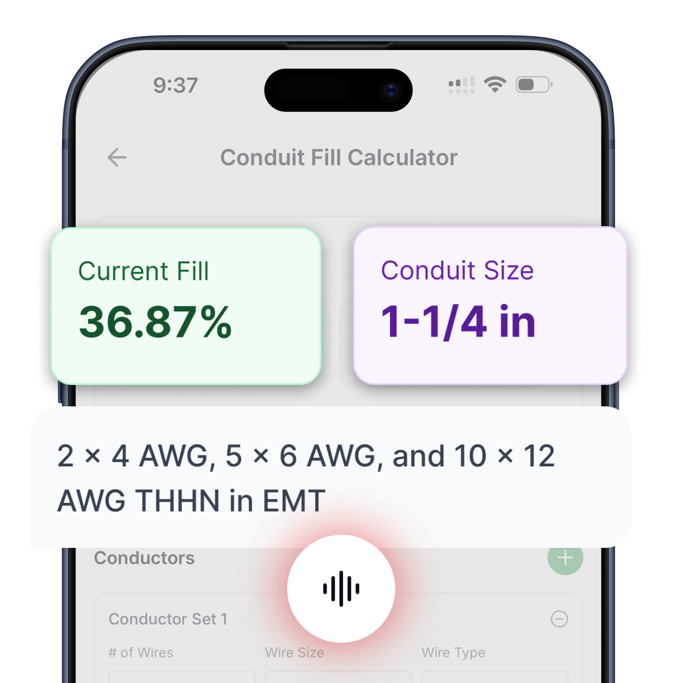
Conduit Fill
Determine minimum conduit size based on conductor count and type. Supports all common conductor insulations and raceway types per NEC Chapter 9.
Try Conduit Calculator ->

Transformer Calculator
Complete primary and secondary sizing for single-phase and three-phase transformers. Includes protection, conductors, bonding jumpers, and raceways.
Try Transformer Calculator ->

Motor Calculator
Get proper breaker and fuse sizing for single-phase and three-phase motors from 1/6 HP to 10 HP. Includes conductor sizing and both breaker and fuse options.
Try Motor Calculator ->

Voltage Drop
Three specialized calculators: find minimum conductor size for a given length, calculate maximum circuit length for a conductor size, or determine actual voltage drop percentage.
Try Voltage Drop Calculator ->

Cooling & Heat Pump Calculator
Size circuits for air conditioning or heat pump equipment using nameplate MCA and MOCP values. Handles single-phase and three-phase systems.
Try Cooling & Heat Pump Calculator ->

Resistive Heating Calculator
Calculate circuits for electric heating equipment including baseboard heaters and unit heaters, based on nameplate ratings. Handles single-phase and three-phase systems.
Try Resistive Heating Calculator ->
Get instant, code-compliant answers with voice commands—no typing, no dropdowns, no hassle.