Select Phase System to See Voltage
Select a load input type above
Fill in the required inputs below to instantly generate breaker size, conductor size, EGC size, raceway size and maximum circuit length.
Enter the conductor details and select a conduit type to calculate fill percentage and required conduit size.
Select Phase System to See Voltage
Fill in the required inputs below to instantly generate protection size, conductor size, EGC size, raceway size and maximum circuit length.
No items added
No items added
No items added
No items added
No items added
No items added
No items added
Enter the square footage of the building to calculate the required electrical service size based on building load.
Fill in the required inputs below to instantly generate protection size, conductor size, EGC size, raceway size and maximum circuit length.
Select Phase System to See Voltage
Fill in the required inputs below to instantly generate protection size, conductor size, EGC size, raceway size and maximum circuit length.
Select Primary Voltage to See Secondary Options
Fill in the required inputs below to instantly generate protection, conductor, EGC, bonding jumper, and raceway sizes for both primary and secondary sides.
Select Phase to See Voltage
Fill in the required inputs below to calculate the voltage drop across your circuit based on conductor size, load, and cable length.
Select Phase to See Voltage
Fill in the required inputs below to calculate the maximum circuit distance allowed before voltage drop exceeds your limit.
Select Phase to See Voltage
Fill in the required inputs below to calculate the minimum conductor size needed to stay within your voltage drop limit.
Select Phase System to See Voltage
Select a load input type above
Fill in the required inputs below to instantly generate breaker size, conductor size, EGC size, raceway size and maximum circuit length.
Enter the conductor details and select a conduit type to calculate fill percentage and required conduit size.
Select Phase System to See Voltage
Fill in the required inputs below to instantly generate protection size, conductor size, EGC size, raceway size and maximum circuit length.
No items added
No items added
No items added
No items added
No items added
No items added
No items added
Enter the square footage of the building to calculate the required electrical service size based on building load.
Fill in the required inputs below to instantly generate protection size, conductor size, EGC size, raceway size and maximum circuit length.
Select Phase System to See Voltage
Fill in the required inputs below to instantly generate protection size, conductor size, EGC size, raceway size and maximum circuit length.
Select Primary Voltage to See Secondary Options
Fill in the required inputs below to instantly generate protection, conductor, EGC, bonding jumper, and raceway sizes for both primary and secondary sides.
Select Phase to See Voltage
Fill in the required inputs below to calculate the voltage drop across your circuit based on conductor size, load, and cable length.
Select Phase to See Voltage
Fill in the required inputs below to calculate the maximum circuit distance allowed before voltage drop exceeds your limit.
Select Phase to See Voltage
Fill in the required inputs below to calculate the minimum conductor size needed to stay within your voltage drop limit.
The dwelling unit load calculator determines the minimum electrical service size required for residential installations based on a comprehensive load analysis. This electrical load calculator follows National Electrical Code (NEC) Article 220 Part III, which provides specific methods for calculating dwelling unit loads that differ significantly from commercial or industrial load calculations.
Understanding these methods ensures residential electrical services are sized adequately for safe operation while avoiding oversizing that wastes materials and money. A licensed electrician can verify that your load calculation meets local code requirements.
Dwelling unit load calculations account for the reality that not all electrical loads operate simultaneously at full capacity.
A home might have 20,000 watts of connected electrical equipment. However, actual peak demand might only reach 12,000 watts because occupants don't use every appliance, light, and outlet simultaneously.
The NEC recognizes this diversity through demand factors that reduce calculated loads to reflect realistic usage patterns.
The calculation process combines multiple load categories, including general lighting and receptacles, small appliance circuits, laundry circuits, fixed appliances, electric ranges, dryers, heating and air conditioning equipment, and electric vehicle charging.
Each category has specific calculation methods and demand factors that reflect typical usage patterns observed in residential occupancies. The final service size represents the peak electrical demand the home is likely to experience under normal operating conditions.
When sizing for large appliances like electric ranges, dryers, and heat pumps, the residential electrical load calculator applies appropriate demand factors. Heat pump equipment and other HVAC loads require special attention in the calculation process to ensure adequate capacity.
General lighting and receptacle load calculations begin with the dwelling's floor area. NEC Table 220.12 specifies 3 volt-amperes per square foot for dwelling units, covering all general-use lighting outlets and general-use receptacle outlets throughout the home.
This area-based calculation captures the combined load of ceiling lights, wall switches, table lamps, televisions, computers, and all the general-purpose receptacles found in every room. An electrical load calculator automates this process for accuracy.
The floor area for load calculations includes all living space within the dwelling's exterior walls. Count all floors of the home, including basements with living space, but exclude open porches, garages, and unfinished attics unless these spaces are adaptable for future use.
Measuring from exterior wall to exterior wall provides the gross floor area, which is then multiplied by 3 VA per square foot.
A 2,000 square foot home has a general lighting and receptacle load of 6,000 volt-amperes (2,000 × 3). This calculated load doesn't require identifying every light fixture or counting every receptacle. The 3 VA per square foot value represents average loading based on decades of residential electrical usage data.
The calculation automatically scales with home size, appropriately sizing larger services for larger homes with more lights and receptacles. A licensed electrician can help interpret these results for your specific installation.
The 3 VA per square foot factor assumes typical residential lighting density and receptacle usage. It covers LED bulbs, incandescent lights, fluorescent fixtures, and the various devices plugged into general-use receptacles.
While individual homes vary in actual usage patterns, the standardized calculation provides consistent service sizing across different dwelling designs and occupant behaviors. A residential electrical load calculator ensures these calculations are performed consistently according to NEC standards.
Small appliance branch circuits serve receptacles in the kitchen, dining room, breakfast room, and pantry where countertop appliances operate. NEC 210.11(C)(1) requires a minimum of two 20-ampere small appliance circuits for every dwelling unit. Each circuit is calculated at 1,500 volt-amperes, totaling 3,000 VA for the two required circuits.
These circuits serve the receptacles where occupants plug in coffee makers, toasters, blenders, mixers, microwaves, and other portable kitchen appliances. The separate calculation for small appliance circuits recognizes that kitchen loads exceed typical general receptacle loads due to heat produced by large appliances and motor loads concentrated in food preparation areas.
When calculating loads for large appliances like a wall oven or cooktop, these are handled separately from small appliance circuits.
Additional small appliance circuits beyond the two required circuits are calculated at 1,500 VA each and added to the total small appliance load. A large kitchen with three or four small appliance circuits would calculate all circuits at 1,500 VA each before applying demand factors.
This approach encourages providing adequate circuits for kitchen needs while properly accounting for the load in service sizing. An electrical load calculator ensures all kitchen circuits are properly accounted for, including dedicated circuits for a wall oven or other built-in appliances.
The small appliance load combines with general lighting and laundry loads before demand factors are applied, as these three categories share common usage characteristics. They represent distributed loads throughout the home that don't all operate continuously at maximum capacity.
The combined treatment reflects realistic diversity in how occupants use lighting, general receptacles, laundry equipment, and kitchen appliances. Your licensed electrician can provide guidance on the number of small appliance circuits needed for your specific kitchen layout.
Every dwelling unit requires at least one 20-ampere laundry circuit per NEC 210.11(C)(2). This dedicated circuit serves the laundry area receptacles where the washing machine plugs in, along with potential additional receptacles for irons or other laundry-related equipment.
The required laundry circuit calculates at 1,500 volt-amperes. When using a residential electrical load calculator, laundry circuits are automatically factored into the total service calculation.
Additional laundry circuits beyond the single required circuit add another 1,500 VA each to the calculated load. Multiple laundry circuits might be installed in larger homes with a dedicated laundry room, or in multi-family buildings where individual units have laundry equipment.
Each circuit contributes to the total load calculation before demand factors reduce the combined value. A licensed electrician can determine if additional laundry circuits are needed for your specific application.
The laundry circuit serves receptacles only, not the electric dryer if one is installed. Electric dryers connect to a separate dedicated circuit calculated independently in the dryer load section.
This separation ensures the washing machine has adequate circuit capacity regardless of dryer installation and allows proper calculation of both appliances in the total service load. Laundry circuits must be dedicated to the laundry area and cannot serve other rooms or areas of the home.
The general lighting load, small appliance load, and laundry circuit load combine into a single total before applying demand factors from NEC Table 220.42. This table recognizes that larger combined loads represent more circuits and receptacles, making it statistically unlikely that all loads operate simultaneously at peak capacity.
The demand factors reduce the calculated load to reflect realistic peak demand. This residential electrical load calculator applies these demand factors automatically for accurate service sizing.
Table 220.42 applies demand factors in tiers based on the total combined load. The first 3,000 volt-amperes is taken at 100%, recognizing that small dwellings typically use most of their lighting and receptacle capacity.
The portion from 3,001 to 120,000 VA is taken at 35%, reflecting significant diversity in larger homes. Any amount exceeding 120,000 VA is taken at 25%, though few single-family homes reach this level.
A dwelling with 6,000 VA general lighting (2,000 sq ft), 3,000 VA small appliance, and 1,500 VA laundry totals 10,500 VA before demand factors.
Applying Table 220.42: the first 3,000 VA is taken at 100% (3,000 VA), and the remaining 7,500 VA is taken at 35% (2,625 VA), for a total demand load of 5,625 VA.
This reduced value represents the realistic peak demand from these combined load categories. An electrical load calculator performs these tiered calculations instantly.
The demand factor application significantly reduces the calculated service size compared to summing all connected loads at full value. This reduction reflects actual residential usage patterns.
In typical homes, not all lights are on, not all receptacles have devices plugged in and operating, and kitchen appliances cycle on and off based on meal preparation timing.
The standardized demand factors provide consistent service sizing while ensuring adequate capacity for peak residential demand. The residential electrical load calculator automatically applies these demand factors to the combined lighting, small appliance, and laundry circuit loads.
Fixed appliances include permanently installed or fastened-in-place equipment such as dishwashers, garbage disposals, trash compactors, water heaters, and built-in microwaves. Each fixed appliance is calculated at its nameplate rating in watts or volt-amperes. Such large appliances require careful consideration when performing a load calculation for any home.
The nameplate provides the actual electrical demand of the specific appliance model installed or planned for the dwelling. Many homeowners and contractors use an electrical load calculator to streamline this process and ensure accuracy.
When four or more fixed appliances are fastened in place, NEC 220.53 allows applying a 75% demand factor to the total of these appliances. This demand factor recognizes that not all fixed appliances operate simultaneously.
A residential electrical load calculator can automatically apply these demand factors to simplify the calculation process.
A dishwasher, garbage disposal, and water heater rarely run at the same instant, creating diversity that reduces peak demand below the sum of individual nameplate ratings.
The 75% demand factor applies only when at least four fixed appliances are present. It applies only to appliances other than electric ranges, clothes dryers, space heating equipment, and air conditioning equipment.
A licensed electrician should verify these calculations to ensure code compliance.
Those specific appliances have separate calculation methods with their own demand factors. The four-appliance threshold ensures sufficient load diversity exists before applying the reduction.
Common fixed appliances in residential calculations include dishwashers at 1,200 to 1,500 watts and garbage disposals at 500 to 900 watts. They also consist of electric water heaters at 3,000 to 5,500 watts and trash compactors at 1,000 to 1,500 watts. These large appliances make up a significant portion of the total electrical demand.
Built-in microwaves add 1,000 to 1,500 watts, while bathroom exhaust fans and similar small motor loads contribute smaller amounts. Adding these nameplate ratings and applying the 75% factor when applicable provides the fixed appliance contribution to total service load.
Your licensed electrician can identify all fixed appliances and ensure their nameplate ratings are correctly included in the calculation.
Electric ranges are calculated using NEC Table 220.55, which provides demand factors specifically for household cooking equipment. This table recognizes that electric ranges rarely operate at full nameplate rating because all burners and the oven don't typically run simultaneously at maximum setting.
Using a residential electrical load calculator can help apply these table values correctly. The demand factors vary based on the number of ranges and their individual ratings.
For a single electric range not exceeding 12 kW nameplate rating, Table 220.55 allows using 8 kW as the demand load. This 8 kW value represents typical peak demand from residential cooking equipment under normal usage.
Ranges with nameplate ratings exceeding 12 kW require adjustments using Column C of the table, but most residential ranges fall within the 12 kW limit.
Multiple ranges in the same dwelling or in multi-family calculations use additional demand factors from Table 220.55. Two ranges calculate at 11 kW total demand (5.5 kW each), three ranges at 14 kW, and the demand percentage continues decreasing as more ranges are added.
These factors reflect the statistical improbability that multiple ranges in different dwelling units all operate at peak capacity simultaneously. A licensed electrician can help determine the appropriate demand factors for multi-family installations.
The range calculation includes the cooktop and built-in ovens in modern kitchens where these components are installed separately. When a separate cooktop and wall ovens are installed, their nameplate ratings are added together and treated as a single range for calculation purposes.
This combined rating then uses Table 220.55 to determine the demand load contribution. A licensed electrician can ensure proper calculations for these split configurations.
Modern electrical load calculator tools can automatically combine wall oven and cooktop loads for accurate load calculation results.
A residential electrical load calculator simplifies the process of applying demand factors from Table 220.55 for various range configurations.
Electric clothes dryers are calculated using NEC Table 220.54, which provides demand factors for dryer loads. Each dryer is calculated at either 5,000 watts or its nameplate rating, whichever is larger.
The dryer load is calculated separately from the laundry circuits that serve the washing machine and laundry area receptacles.
This 5,000-watt minimum recognizes that most residential dryers draw substantial current for their heating elements and motor, even if specific models might have slightly lower ratings. A residential electrical load calculator simplifies this comparison and ensures the correct value is used.
Single-dwelling-unit calculations typically include one dryer at 5,000 watts or the nameplate rating. This value goes directly into the service load calculation without demand factors for a single dryer.
The dryer operates on a dedicated 240-volt circuit, typically protected by a 30-ampere circuit breaker to handle the approximately 20- 24-ampere full-load current of standard residential dryers.
Multiple dryers in multi-family calculations use demand factors from Table 220.54. For one through four dryers, the demand factor is 100; no reduction is applied. The first reduction tier begins at five dryers (85%), followed by six dryers at 75%, seven dryers at 65%, and continuing to decrease for larger numbers of dryers.
These demand factors become relevant primarily in apartment buildings or multi-family installations where load diversity across multiple units reduces peak demand. An electrical load calculator with multi-family capabilities can streamline these more complex calculations.
The separation of laundry circuits from the dryer circuit ensures both the washing machine and dryer have adequate capacity. The laundry circuit serves the washing machine and other laundry receptacles, while the dryer has its dedicated circuit and separate load calculation.
Both laundry circuits and dryer circuits contribute to the total dwelling unit service load, but they represent distinct electrical requirements with different usage patterns and demand characteristics.
Laundry circuits typically require a 20-ampere branch circuit in addition to the dedicated dryer circuit. When planning laundry circuits, a licensed electrician will ensure both the washer receptacle and dryer circuit meet NEC requirements.
Heating and air conditioning loads are treated as noncoincidental loads, meaning they don't operate simultaneously. NEC 220.60 requires including only the larger of the heating or air conditioning load in the service calculation.
A home with both central air conditioning and electric heat includes only whichever system draws more current, not both at the same time. A residential electrical load calculator automatically compares these values to include only the larger load.
The air conditioning load uses the nameplate rating from the outdoor condensing unit, including compressor and condenser fan motor loads. Heat pump systems are calculated similarly, using the heat pump compressor load.
The air conditioning or heat pump load goes directly into the service calculation at 100% of the nameplate value without demand factors, recognizing that cooling equipment operates at full capacity during peak cooling periods.
An electrical load calculator ensures these large appliances are properly accounted for at their full nameplate ratings.
Electric heating equipment includes baseboard heaters, unit heaters, and heat pump auxiliary heating strips. The total connected heating load combines all heating equipment in the dwelling, and then this total is compared to the air conditioning load.
Whichever is larger determines what value enters the service calculation for the heating/cooling category. A licensed electrician should verify this comparison to ensure code compliance.
Heat pump auxiliary heat presents a special case because it supplements the heat pump compressor during cold weather. When calculating the heating load for comparison to air conditioning, use the heat pump compressor load plus the auxiliary heat strips if they can operate simultaneously.
This combined heating load then compares against the cooling load (heat pump in cooling mode) to determine which is larger. Using an electrical load calculator helps properly account for all heating components when dealing with heat pump systems.
If the heating and cooling loads are close in value, an important consideration is that when the smaller of the two loads is also a motor or air conditioning load, NEC 220.60 requires including 25% of that smaller load in addition to the full value of the larger load.
This accounts for the higher starting current from motor-compressor equipment. For example, if heating is 12,000 VA and cooling is 10,000 VA, include the full 12,000 VA heating plus 25% of the 10,000 VA cooling (2,500 VA) for a total of 14,500 VA from this category.
Electric vehicle supply equipment (EVSE) is calculated at 7,200 volt-amperes minimum per NEC 220.57, or the actual nameplate rating if higher. Most Level 2 residential EV chargers operate at 240 volts and draw 30 to 40 amperes, translating to 7,200 to 9,600 VA.
The calculation uses whichever is larger: the 7,200 VA minimum or the actual equipment rating. Using an electrical load calculator helps ensure accurate EVSE load calculations.
EVSE represents a continuous load because vehicle charging sessions extend for several hours. The equipment nameplate already accounts for this continuous operation in its rating, so the value goes directly into the load calculation without additional multipliers.
Modern EVSEs include their own protective devices and current limiting to prevent overload.
Multiple EVSE installations in single-family homes are becoming more common as households acquire multiple electric vehicles. Each EVSE is calculated at its nameplate rating or 7,200 VA minimum, with all EVSE loads summed before adding to the total service load. Future dwelling unit calculations should consider EVSE loads even if not initially installed, as adding charging equipment later may require service upgrades.
The substantial load from EVSE often drives service size decisions in modern residential construction. A home with two EVSEs adds 14,400 to 19,200 VA to the service load, which can push total demand into the range requiring 200-ampere or larger service. Planning for EVSE during initial construction allows proper service sizing and avoids costly upgrades later.
Motors and motor-operated equipment beyond those already counted in other categories are calculated at their nameplate ratings. This category includes well pumps, swimming pool pumps, hot tub motors, whole-house fans, and similar motor loads. Each motor contributes its nameplate wattage or volt-amperage to the total service calculation.
Swimming pool pump motors represent a common residential motor load, typically ranging from three-quarters to two horsepower. These motors operate for many hours daily to maintain water circulation and filtration, making them significant contributors to service load. A 1.5 HP pool pump at 240 volts, single-phase, draws approximately 2,000 watts based on typical motor efficiency.
Well pumps in rural homes without a municipal water supply represent another substantial motor load. Submersible well pumps range from one-half to two horsepower, depending on well depth and water demand.
A one HP well pump adds approximately 1,500 to 2,000 watts to the service load calculation. These pumps cycle on and off based on pressure tank demand, but the service must handle full pump current when it operates.
Hot tub and spa motors include both circulation pumps and jet pumps, with combined loads often reaching 3,000 to 5,000 watts. The nameplate rating on the hot tub control panel provides the total electrical demand, including heaters and motors.
This nameplate value enters the service calculation directly, as the equipment already accounts for the combined load of all components.
Any electrical equipment not covered in the previous categories gets added to the service load calculation at its nameplate rating. This catch-all category ensures every electrical load in the dwelling is accounted for in the final service size determination.
Examples include electric vehicle lifts in home garages, large workshop equipment, commercial-grade kitchen equipment, or specialized hobby equipment requiring dedicated circuits.
Home workshop equipment might include table saws, air compressors, welding equipment, or other tools with significant electrical demands. While these loads may not operate continuously, they must be included in service sizing if they're permanently installed or represent regular usage. The nameplate rating of each piece of equipment contributes to this category's total.
Backup generators with automatic transfer switches don't add to the service load calculation because they provide power rather than consuming it.
However, the loads served by the generator during a utility outage should be included in the normal service calculation since those loads also operate during normal utility-supplied power conditions.
The final service load combines all categories after applying appropriate demand factors: the demand-adjusted lighting/small appliance/laundry load, fixed appliances with 75% demand if applicable, electric range at its Table 220.55 value, dryer load, the larger of heating or cooling (with 25% of the smaller if applicable), EVSE load, motor loads, and any other equipment loads. This total represents the peak volt-ampere demand for the dwelling.
Converting total demand from volt-amperes to amperes requires dividing by the service voltage. Standard residential services use 240 volts for this calculation: Service Amperes = Total VA ÷ 240 V.
A dwelling with 30,000 VA total demand calculates to 125 amperes (30,000 ÷ 240). This amperage represents the minimum service rating required by the NEC.
Standard residential service sizes include 100, 125, 150, 200, 225, and 400 amperes. The calculated minimum must be rounded up to the next standard service size.
A calculated 125 amperes requires a minimum 125-ampere service, while 126 amperes would require rounding up to 150 amperes. Using standard service sizes ensures compatibility with available service equipment and utility company metering.
The recommended service size typically exceeds the calculated minimum to provide capacity for future load additions and to avoid operating the service near its maximum rating.
Operating electrical services at 80-90% of rated capacity leaves a margin for unexpected peak demands and provides headroom for adding equipment without service upgrades.
Most modern homes install 200-ampere service even when calculations show 150 amperes would meet minimum requirements. The cost difference between150-0 and 200-ampere service equipment is modest compared to the cost of upgrading service later when adding load.
Solar panels, electric vehicles, hot tubs, or workshop equipment might be added years after initial construction, and adequate initial service sizing prevents costly retrofits.
Homes with substantial electric heating, multiple EVSE installations, or extensive motor loads may require200-0 or 400-ampere service based on calculated demand. Large homes exceeding 4,000 square feet often benefit from 400-ampere service, providing ample capacity for current and future loads.
The utility company can provide guidance on service size options and any limitations based on available transformer capacity.
Understanding how different load categories contribute to total service demand helps identify opportunities for load management or efficiency improvements.
A breakdown showing volt-amperes from each category reveals whether the service is driven primarily by heating/cooling, appliances, general loads, or EVSE. This information guides decisions about equipment selection and energy management.
Heating and cooling loads often represent the largest single category in total service demand. Homes using electric heating or heat pumps with substantial auxiliary heat may see 40-50% of service capacity dedicated to climate control.
This concentration suggests that heating/cooling efficiency improvements provide the most benefit for reducing electrical demand and potentially avoiding service upgrades.
EVSE loads are becoming increasingly dominant in service calculations as electric vehicle adoption grows. Two EVSEs can represent 15-20% of the total service load in a typical home.
Smart EVSE systems with load management capability can reduce peak demand by staggering charging times or limiting total current, potentially allowing smaller service sizes than would otherwise be required.
NEC 220.82 provides an optional calculation method for dwelling units as an alternative to the standard method. The optional method often results in smaller calculated service sizes by applying more aggressive demand factors reflecting realistic diversity in modern electrical usage.
However, the optional method has specific requirements and limitations that restrict when it can be used.
The optional calculation method requires all heating and cooling equipment to be permanently installed. It allows the application of demand factors to the total connected load, including general lighting, appliances, and equipment.
For dwellings with electric heating or air conditioning loads at least equal to or greater than the nonheating/cooling portions. For these dwellings, it can provide significant load reduction compared to standard calculations.
Most residential calculations use the standard method because it's more straightforward and doesn't require meeting specific prerequisites about heating equipment installation. The standard method provides conservative service sizing that ensures adequate capacity under all loading conditions.
For complex installations or situations where service size limitations exist, consulting with electrical engineers or licensed electricians about the optional method may identify opportunities for smaller service sizing.
Individual dwelling units within multi-family buildings (apartments, condominiums, townhouses) each require load calculations to size the unit's feeder from the building service. These calculations follow the same methods as single-family homes, accounting for the square footage, large appliances, and equipment within each unit.
The unit feeders then combine at the building service with additional demand factors applied.
Multi-family building services benefit from demand diversity across multiple dwelling units. Not all units experience peak demand simultaneously, allowing the building service to be sized smaller than the sum of individual unit loads.
NEC Table 220.84 provides demand factors for feeders serving multiple dwelling units, with larger numbers of units allowing greater demand reduction.
Common area loads in multi-family buildings must be calculated separately and added to the total building service load. Common areas include lobbies, hallways, laundry rooms, parking garage lighting, elevators, and building mechanical systems.
These loads use standard commercial calculation methods rather than dwelling unit factors.
The dwelling unit load calculation determines service size, but doesn't eliminate requirements for specific branch circuits. NEC 210.11 requires two small appliance circuits, one laundry circuit, bathroom receptacle circuits, and individual circuits for some large appliances, regardless of the total calculated service load.
These circuit requirements ensure adequate distribution of loads and prevent overloading individual circuits.
A dwelling with a calculated service demand of 100 amperes still needs all required branch circuits properly sized and protected. The service calculation shows total capacity needed, while branch circuit requirements ensure loads are distributed appropriately throughout the panelboard.
Both requirements must be met for code-compliant installations.
Large appliances typically require dedicated circuits sized per their specific nameplate rating requirements. Electric ranges, dryers, water heaters, air conditioning equipment, and EVSE all need individual circuits.
The service calculation accounts for these loads, and the branch circuit requirements ensure proper individual circuit sizing and protection. Large appliances such as electric ranges and dryers demand significant power, making proper circuit protection essential for safety and performance.
Residential load calculations should consider likely future additions even if equipment isn't initially installed. Provisions for future EVSE, hot tubs, or workshop equipment influence service size selection.
Installing a 200-ampere service initially costs far less than upgrading from 100 to 200 amperes later, making some oversizing economically justified.
Solar panel installations don't typically require larger service sizes because solar provides power rather than consuming it. However, some solar installations include battery backup systems with substantial charging loads that must be included in service calculations.
Consulting with solar installers during initial design helps identify any service sizing implications.
Kitchen renovations often add electrical load through additional appliances or upgraded cooking equipment. Planning for potential kitchen expansion when sizing initial service prevents limitations on future remodeling.
Large appliances added during kitchen upgrades can significantly increase electrical demand beyond original calculations.
The modest additional cost of larger service equipment during initial construction provides flexibility for decades of future occupancy.
All dwelling unit load calculations reference NEC Article 220, providing standardized methods that electrical inspectors recognize and accept. Proper calculation documentation helps with permit applications and demonstrates professional installation practices.
Maintaining records of load calculations assists with future modifications or when explaining service capacity to homeowners. A qualified licensed electrician should perform these calculations to ensure accuracy and code compliance.
Utility companies may have specific requirements for service size, metering equipment, or service entrance configuration that affect installation details beyond the load calculation.
Coordinating with the utility during design ensures the proposed service meets both NEC requirements and utility standards. Some utilities provide service calculation assistance or review as part of their new construction support.
Service size directly affects utility connection costs in some jurisdictions. Larger services may incur higher connection fees or require transformer upgrades at the utility's expense.
Understanding utility policies helps with project budgeting and may influence decisions about service sizing when calculated loads fall between standard service sizes. Large appliances and their electrical requirements should be discussed with both the utility company and installation professionals to ensure proper service capacity and connection.

Circuit Calculations
Size conductors, breakers, and raceways for any branch circuit or feeder. Includes automatic voltage drop calculations and equipment grounding conductor sizing.
Try Circuit Calculator ->

Load Calculator
Complete dwelling unit load calculations following NEC Article 220. Size service conductors and calculate demand loads for residential installations.
Try Load Calculator ->

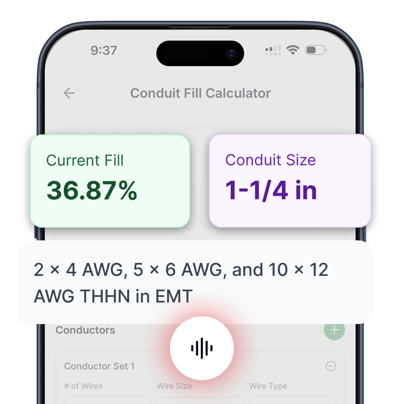
Conduit Fill
Determine minimum conduit size based on conductor count and type. Supports all common conductor insulations and raceway types per NEC Chapter 9.
Try Conduit Calculator ->

Transformer Calculator
Complete primary and secondary sizing for single-phase and three-phase transformers. Includes protection, conductors, bonding jumpers, and raceways.
Try Transformer Calculator ->

Motor Calculator
Get proper breaker and fuse sizing for single-phase and three-phase motors from 1/6 HP to 10 HP. Includes conductor sizing and both breaker and fuse options.
Try Motor Calculator ->

Voltage Drop
Three specialized calculators: find minimum conductor size for a given length, calculate maximum circuit length for a conductor size, or determine actual voltage drop percentage.
Try Voltage Drop Calculator ->

Cooling & Heat Pump Calculator
Size circuits for air conditioning or heat pump equipment using nameplate MCA and MOCP values. Handles single-phase and three-phase systems.
Try Cooling & Heat Pump Calculator ->

Resistive Heating Calculator
Calculate circuits for electric heating equipment including baseboard heaters and unit heaters, based on nameplate ratings. Handles single-phase and three-phase systems.
Try Resistive Heating Calculator ->
Get instant, code-compliant answers with voice commands—no typing, no dropdowns, no hassle.