Select Phase System to See Voltage
Select a load input type above
Fill in the required inputs below to instantly generate breaker size, conductor size, EGC size, raceway size and maximum circuit length.
Enter the conductor details and select a conduit type to calculate fill percentage and required conduit size.
Select Phase System to See Voltage
Fill in the required inputs below to instantly generate protection size, conductor size, EGC size, raceway size and maximum circuit length.
No items added
No items added
No items added
No items added
No items added
No items added
No items added
Enter the square footage of the building to calculate the required electrical service size based on building load.
Fill in the required inputs below to instantly generate protection size, conductor size, EGC size, raceway size and maximum circuit length.
Select Phase System to See Voltage
Fill in the required inputs below to instantly generate protection size, conductor size, EGC size, raceway size and maximum circuit length.
Select Primary Voltage to See Secondary Options
Fill in the required inputs below to instantly generate protection, conductor, EGC, bonding jumper, and raceway sizes for both primary and secondary sides.
Select Phase to See Voltage
Fill in the required inputs below to calculate the voltage drop across your circuit based on conductor size, load, and cable length.
Select Phase to See Voltage
Fill in the required inputs below to calculate the maximum circuit distance allowed before voltage drop exceeds your limit.
Select Phase to See Voltage
Fill in the required inputs below to calculate the minimum conductor size needed to stay within your voltage drop limit.
Select Phase System to See Voltage
Select a load input type above
Fill in the required inputs below to instantly generate breaker size, conductor size, EGC size, raceway size and maximum circuit length.
Enter the conductor details and select a conduit type to calculate fill percentage and required conduit size.
Select Phase System to See Voltage
Fill in the required inputs below to instantly generate protection size, conductor size, EGC size, raceway size and maximum circuit length.
No items added
No items added
No items added
No items added
No items added
No items added
No items added
Enter the square footage of the building to calculate the required electrical service size based on building load.
Fill in the required inputs below to instantly generate protection size, conductor size, EGC size, raceway size and maximum circuit length.
Select Phase System to See Voltage
Fill in the required inputs below to instantly generate protection size, conductor size, EGC size, raceway size and maximum circuit length.
Select Primary Voltage to See Secondary Options
Fill in the required inputs below to instantly generate protection, conductor, EGC, bonding jumper, and raceway sizes for both primary and secondary sides.
Select Phase to See Voltage
Fill in the required inputs below to calculate the voltage drop across your circuit based on conductor size, load, and cable length.
Select Phase to See Voltage
Fill in the required inputs below to calculate the maximum circuit distance allowed before voltage drop exceeds your limit.
Select Phase to See Voltage
Fill in the required inputs below to calculate the minimum conductor size needed to stay within your voltage drop limit.
The resistive heating calculator sizes electrical circuits for fixed electric heating equipment based on manufacturer nameplate information. Electric heating presents unique circuit requirements because heating loads operate continuously during cold weather, running for extended periods that trigger the continuous load provisions in the National Electrical Code (NEC).
Understanding these requirements ensures heating systems operate safely and reliably when they're needed most.
Fixed electric heating equipment includes baseboard heaters, wall-mounted unit heaters, radiant ceiling panels, and other permanently installed heating devices.
These systems convert electrical energy directly into heat through resistive elements, making them highly efficient at the point of use. This efficiency is achieved through joule heating, the process where electrical current flowing through resistance generates thermal energy.
The nameplate on each heating unit provides the critical information needed for proper circuit sizing: the maximum overcurrent protection rating and the minimum circuit ampacity.
Manufacturers test their equipment and determine the appropriate protection and circuit ampacity values based on the heating elements, internal wiring, and control components. These nameplate values establish the starting point for all circuit calculations.
Unlike general circuits, where you might calculate protection size from load, heating equipment provides specific protection limits that must not be exceeded to maintain equipment warranty and safety listings.
The nameplate Maximum Overcurrent Protection (MOP) rating tells you the largest circuit breaker or fuse that can protect the heating equipment. This value comes from manufacturer testing and accounts for the inrush current when heating elements first energize, the steady-state operating current, and the thermal characteristics of internal components.
Exceeding this maximum protection size can allow fault currents that damage the equipment before the overcurrent device trips.
Protection devices must clear faults before conductors or equipment reach dangerous temperatures. Heating equipment contains temperature-sensitive components, including thermostats, limit switches, and wire insulation rated for specific maximum temperatures.
The nameplate maximum protection ensures these components stay within their safe operating ranges even during fault conditions or when multiple heating stages operate simultaneously.
The minimum circuit ampacity tells you the smallest conductor ampacity that can safely supply the heating load. This value already includes the 125% factor required for continuous loads, so you don't need to apply additional multiplication.
Manufacturers calculate this value based on the heating element wattage, voltage, and expected operating duration. Using conductors with ampacity below this minimum can result in a voltage drop that prevents the heater from reaching the target temperature, or excessive conductor heating that degrades insulation over time due to increased thermal resistance.
Protection sizing for resistive heating follows NEC Article 424, which covers fixed electric space-heating equipment. The calculator uses the nameplate maximum overcurrent protection value directly as the protection size.
This differs from general circuit calculations where you compute protection size from load current because heating equipment manufacturers have already determined the appropriate protection through testing and engineering analysis.
The nameplate maximum protection accounts for the specific characteristics of the heating equipment. Some units have multiple heating stages that can all energize simultaneously, creating brief periods of very high current draw and heat generation.
Others include motors for fans or blowers that add motor starting current to the resistive heating load. The manufacturer's protection rating considers all these factors to establish a safe maximum value.
Standard overcurrent device ratings follow specific increments: 15, 20, 30, 40, 50, 60, and continuing upward. If the nameplate specifies a maximum protection of 60 amperes, you must use a 60-ampere or smaller overcurrent device.
You cannot round up to the next standard size as you might with other types of loads. This restriction protects the equipment's internal components and maintains compliance with its listing requirements.
Conductor sizing for heating circuits uses NEC Article 424.3(B), which requires conductors to have an ampacity not less than 125% of the total heating load.
However, the nameplate minimum circuit ampacity already includes this 125% factor, so you can select conductors directly from NEC Table 310.16 based on the nameplate MCA value. This simplifies the calculation while ensuring code compliance for the power system.
The ampacity tables in NEC 310.16 list conductor current-carrying capacity based on three variables: conductor size, conductor material (copper or aluminum), and temperature rating (60°C, 75°C, or 90°C).
Commercial installations typically use the 75°C column because most circuit breakers and equipment terminals are rated for 75°C connections. Residential heating circuits may use 60°C ratings, particularly for smaller branch circuits supplying individual baseboard heaters where proper thermal management ensures safe operation.
Temperature rating selection affects which column of Table 310.16 you use for conductor selection. A 12 AWG copper conductor has different ampacity ratings depending on temperature: 20 amperes at 60°C, 25 amperes at 75°C, and 30 amperes at 90°C.
The higher temperature ratings allow conductors to safely carry more current because the insulation can withstand higher operating temperatures without degradation. These ratings also facilitate better heat transfer away from the conductor.
The conductor rating output shows the actual ampacity of the selected conductor from Table 310.16. This value will meet or exceed the nameplate minimum circuit ampacity.
The difference between the conductor rating and the actual heating load provides some capacity margin for voltage drop compensation and future heating additions. However, you should not rely on this margin for significant load increases.
Electric heating represents one of the clearest examples of continuous loads in electrical systems. During winter operation, heating systems run for hours at a time, maintaining space temperature.
The NEC defines continuous loads as those expected to operate for three hours or more, and heating equipment clearly meets this definition during the coldest weather.
The 125% factor applied to continuous loads accounts for the power dissipation and I-squared-R heating that occurs in conductors carrying current. When current flows through a conductor, the conductor heats up proportionally to the square of the current.
This heating is normally insignificant for short-duration loads, but extended operation at full load can raise conductor temperature enough to degrade insulation or overheat surrounding materials.
Heating circuits often operate at their full rated load whenever the thermostat calls for heat. Unlike lighting circuits where only some fixtures might be on, or receptacle circuits where actual load varies significantly, heating circuits draw their full nameplate current during operation.
This consistent loading makes proper conductor sizing critical for safe operation throughout the heating season.
The temperature rise in conductors affects not just the conductors themselves but also the surrounding environment. Conductors bundled with other circuits in insulated walls or passing through thermal insulation experience reduced heat dissipation.
The 125% continuous load factor provides thermal margin to prevent excessive temperature rise even when heat dissipation is restricted.
Equipment grounding conductor sizing comes from NEC Table 250.122, using the circuit protection size as the lookup value. The table provides minimum grounding conductor sizes that ensure adequate fault current capacity to trip overcurrent devices during ground faults.
Proper grounding is essential for heating equipment because metal enclosures and heating elements can become energized during insulation failures.
Ground fault protection is particularly important for heating equipment because heating elements operate at high temperatures that can accelerate insulation breakdown. Water heaters, space heaters, and other heating equipment often operate in damp or humid environments that increase ground fault risk. The equipment grounding conductor provides the low-impedance path needed to clear these faults quickly.
The grounding conductor size increases with circuit protection size because larger circuits must clear higher fault currents. A circuit protected by a 60-ampere breaker requires a 10 AWG copper equipment grounding conductor, while a 100-ampere circuit needs an 8 AWG copper ground.
These sizes ensure the grounding conductor can carry fault current without melting or creating dangerous voltage drops during the fault-clearing time.
Aluminum equipment grounding conductors require larger sizes than copper due to aluminum's higher resistance. If you select aluminum for the circuit conductors, the calculator adjusts the equipment grounding conductor size from Table 250.122 to account for this difference.
Many installations use copper for grounding even when circuit conductors are aluminum because copper's superior conductivity provides better fault-clearing performance.
Raceway sizing follows NEC Chapter 9 requirements, accounting for the current-carrying conductors and the equipment grounding conductor. The calculator assumes THHN insulation in EMT conduit, which represents the most common installation method for commercial heating circuits.
Conductor cross-sectional areas come from Chapter 9, Table 5, which lists dimensions for insulated conductors, including the insulation thickness.
Heating circuits typically include two current-carrying conductors for single-phase installations: one hot and one neutral. The equipment grounding conductor adds to the total conductor count and area but doesn't carry load current under normal conditions.
All three conductors must fit within the raceway while maintaining the 40% fill limit that applies when installing three or more conductors.
The raceway size calculation becomes more complex when multiple heating circuits share a common raceway. Each circuit's conductors contribute to the total fill, and the combined area of all conductors determines the minimum raceway size.
Installing multiple heating circuits in a single raceway can be economical but requires careful calculation to ensure code compliance and avoid installation difficulties.
Conduit fill near the maximum 40% limit makes wire pulling difficult, particularly for longer runs. Heating circuits often run considerable distances from the panel to heating equipment locations, so slightly oversizing the raceway above the calculated minimum can significantly ease installation.
The additional cost of one size larger conduit is often justified by reduced labor for pulling conductors.
Maximum circuit length calculations account for voltage drop that can prevent heating equipment from reaching its rated output. The calculator uses the nameplate minimum circuit ampacity as the current value for voltage drop calculations, applying the standard 3% limit for branch circuits.
Excessive voltage drop reduces the voltage available at the heating equipment, which decreases heat output proportionally.
Resistive heating loads are particularly sensitive to voltage drop because heat output varies with the square of the applied voltage. A heating element rated for 240 volts that receives only 230 volts due to a voltage drop produces approximately 92% of its rated heat output.
In cold weather, this reduction can mean the difference between maintaining comfortable temperatures and falling behind on heating demand.
Single-phase heating circuits use a voltage drop multiplier of 2 to account for current flow in both the supply and return conductors. The voltage drop accumulates in both the hot conductor carrying current to the load and the neutral conductor returning current to the source.
Three-phase heating equipment uses a multiplier of 1.73 (the square root of 3), reflecting the more efficient voltage drop characteristics of three-phase systems.
Conductor resistance increases with length and decreases with conductor size. Larger conductors have lower resistance per foot, allowing longer circuit runs before reaching the voltage drop limit.
Copper conductors have lower resistance than aluminum, providing better voltage drop performance for the same conductor size. The calculator uses resistance values from the National Electrical Code (NEC) Chapter 9, Table 8 for DC resistance, which provides conservative results for heating circuits operating at 60 Hz.
Single-phase heating equipment operates at common voltages including 120, 208, 240, and 277 volts. The voltage selection affects current draw for a given wattage load, with higher voltages resulting in lower current.
A 4800-watt heater draws 20 amperes at 240 volts but would draw 40 amperes at 120 volts. Using higher voltage reduces conductor size requirements and improves voltage drop performance.
Three-phase heating equipment finds common use in commercial and industrial processes where large heating loads are needed. Three-phase systems distribute power more evenly and allow smaller conductor sizes for a given total wattage.
Common three-phase voltages include 208, 240, and 480 volts. The phase configuration and voltage must match between the electrical supply and the heating equipment for proper operation.
Voltage selection impacts both the heating equipment and the electrical distribution system. Commercial buildings with 480/277-volt electrical systems often use 277-volt heating to take advantage of existing distribution voltages and avoid transformation costs.
Residential installations typically use 240 volts for electric heating because this voltage is readily available from standard 120/240-volt services.
Commercial heating installations typically require 75°C conductor ratings because commercial circuit breakers and equipment terminals are rated for 75°C connections. The 75°C column in Table 310.16 provides the appropriate ampacity values for conductor selection.
Commercial buildings often have larger heating loads requiring larger conductors, multiple heating zones with dedicated circuits, and more complex control systems.
Residential heating circuits may use 60°C conductor ratings, particularly for smaller branch circuits supplying individual baseboard heaters or wall heaters. Residential circuit breakers rated 100 amperes and below often have terminals rated for 60°C or 75°C connections, with the lower rating typically governing.
Checking the circuit breaker specifications helps determine which temperature rating applies to your installation.
The temperature rating affects conductor sizing significantly for smaller wire gauges. A 12 AWG copper conductor is rated for 20 amperes at 60°C but 25 amperes at 75°C.
This difference can determine whether a heating circuit requires 12 AWG or 10 AWG conductors. Using the correct temperature rating ensures conductors match the thermal capabilities of the overcurrent device and equipment terminals.
Heating circuit installations benefit from careful planning of circuit routing and equipment placement. Locating heating equipment as close as reasonably possible to the electrical panel reduces circuit length, minimizes voltage drop, and lowers installation costs.
When long circuit runs are unavoidable, consider increasing conductor size beyond the minimum required to maintain adequate voltage at the heating equipment.
Grouping multiple heating circuits in a common raceway requires derating calculations beyond what the basic heating calculator provides. When more than three current-carrying conductors share a raceway, the ampacity of each conductor must be reduced according to NEC 310.15(C)(1) adjustment factors.
This derating accounts for the cumulative heat generated by multiple conductors in close proximity, which reduces their heat dissipating capability.
Heating thermostats and controls should be located where they accurately sense space temperature without influence from heat sources, cold drafts, or direct sunlight. The electrical connections to thermostats typically use smaller wire than the heating circuit itself, but these control conductors still require proper sizing and protection.
Low-voltage thermostats need transformers sized appropriately for the control load and wire length.
Baseboard heating typically uses multiple individual heaters, each on its own circuit or with several heaters sharing a circuit. The nameplate on each heater provides wattage and voltage, which determine current draw.
Multiple heaters on a single circuit add their currents together, and the circuit must be sized for the combined load. Most residential baseboard circuits use a 240-volt supply with 20- or 30-ampere protection.
Unit heaters with fans combine resistive heating elements and motor loads. The nameplate provides combined ratings that account for both the heating and fan loads.
Some larger unit heaters require three-phase power for their fan motors, even though the heating elements work equally well on single- or three-phase supply. The nameplate ratings cover all components for simplified circuit sizing.
Radiant heating systems include electric radiant floor heating and ceiling panels. These systems often operate at lower wattage per square foot than forced-air systems but cover large areas, resulting in substantial circuit loads.
Radiant heating mats come with specific amperage ratings and maximum circuit protection requirements. Multiple heating zones allow better temperature control and can spread electrical load across multiple circuits.
When heating equipment fails to reach the target temperature, a voltage drop is a common culprit. Measuring voltage at the equipment during operation and comparing it to the rated voltage helps diagnose voltage drop problems.
A drop exceeding 3% of the rated voltage indicates conductors may be undersized for the circuit length, or loose connections may be creating additional resistance.
Correcting voltage drop problems requires either increasing conductor size or reducing circuit length. In existing installations, increasing conductor size means pulling new, larger conductors through existing raceways.
Verify the larger conductors will fit within raceway fill limits before starting this work. Alternatively, relocating the heating equipment closer to the power source or installing a sub-panel near the heating load can reduce circuit length.
Voltage drop affects all equipment on the circuit, not just heating loads. If lighting or other equipment shares the circuit with heating, those devices also experience reduced voltage when the heating operates.
Dedicated heating circuits avoid these interactions and simplify troubleshooting when problems occur.
All heating circuit calculations reference NEC Article 424 for fixed electric space-heating equipment, along with the general wiring requirements in Articles 210, 250, and 310.
These references provide the foundation for code-compliant installations and give inspectors the information needed to verify proper circuit sizing.
Maintaining calculation records demonstrates professional installation practices and helps with future modifications or additions.
Manufacturer installation instructions often include additional requirements beyond the basic NEC provisions. These instructions might specify minimum clearances from combustible materials, maximum circuit length, or specific installation methods.
Following manufacturer instructions maintains equipment warranty coverage and ensures safe operation throughout the equipment's service life.
Electric heating loads contribute significantly to building electrical demand, affecting service and feeder sizing. Documenting each heating circuit's load helps with demand calculations and future electrical system planning.
When buildings add heating capacity, knowing the existing heating load helps determine whether service upgrades are needed or whether capacity exists for additional circuits.

Circuit Calculations
Size conductors, breakers, and raceways for any branch circuit or feeder. Includes automatic voltage drop calculations and equipment grounding conductor sizing.
Try Circuit Calculator ->

Load Calculator
Complete dwelling unit load calculations following NEC Article 220. Size service conductors and calculate demand loads for residential installations.
Try Load Calculator ->

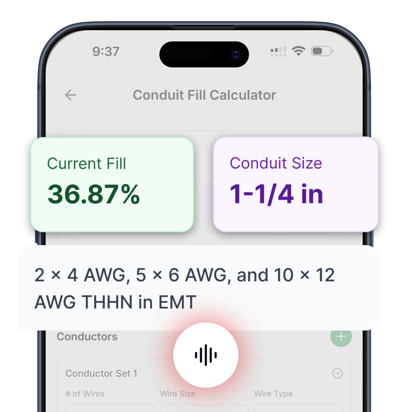
Conduit Fill
Determine minimum conduit size based on conductor count and type. Supports all common conductor insulations and raceway types per NEC Chapter 9.
Try Conduit Calculator ->

Transformer Calculator
Complete primary and secondary sizing for single-phase and three-phase transformers. Includes protection, conductors, bonding jumpers, and raceways.
Try Transformer Calculator ->

Motor Calculator
Get proper breaker and fuse sizing for single-phase and three-phase motors from 1/6 HP to 10 HP. Includes conductor sizing and both breaker and fuse options.
Try Motor Calculator ->

Voltage Drop
Three specialized calculators: find minimum conductor size for a given length, calculate maximum circuit length for a conductor size, or determine actual voltage drop percentage.
Try Voltage Drop Calculator ->

Cooling & Heat Pump Calculator
Size circuits for air conditioning or heat pump equipment using nameplate MCA and MOCP values. Handles single-phase and three-phase systems.
Try Cooling & Heat Pump Calculator ->

Resistive Heating Calculator
Calculate circuits for electric heating equipment including baseboard heaters and unit heaters, based on nameplate ratings. Handles single-phase and three-phase systems.
Try Resistive Heating Calculator ->
Get instant, code-compliant answers with voice commands—no typing, no dropdowns, no hassle.