Select Phase System to See Voltage
Select a load input type above
Fill in the required inputs below to instantly generate breaker size, conductor size, EGC size, raceway size and maximum circuit length.
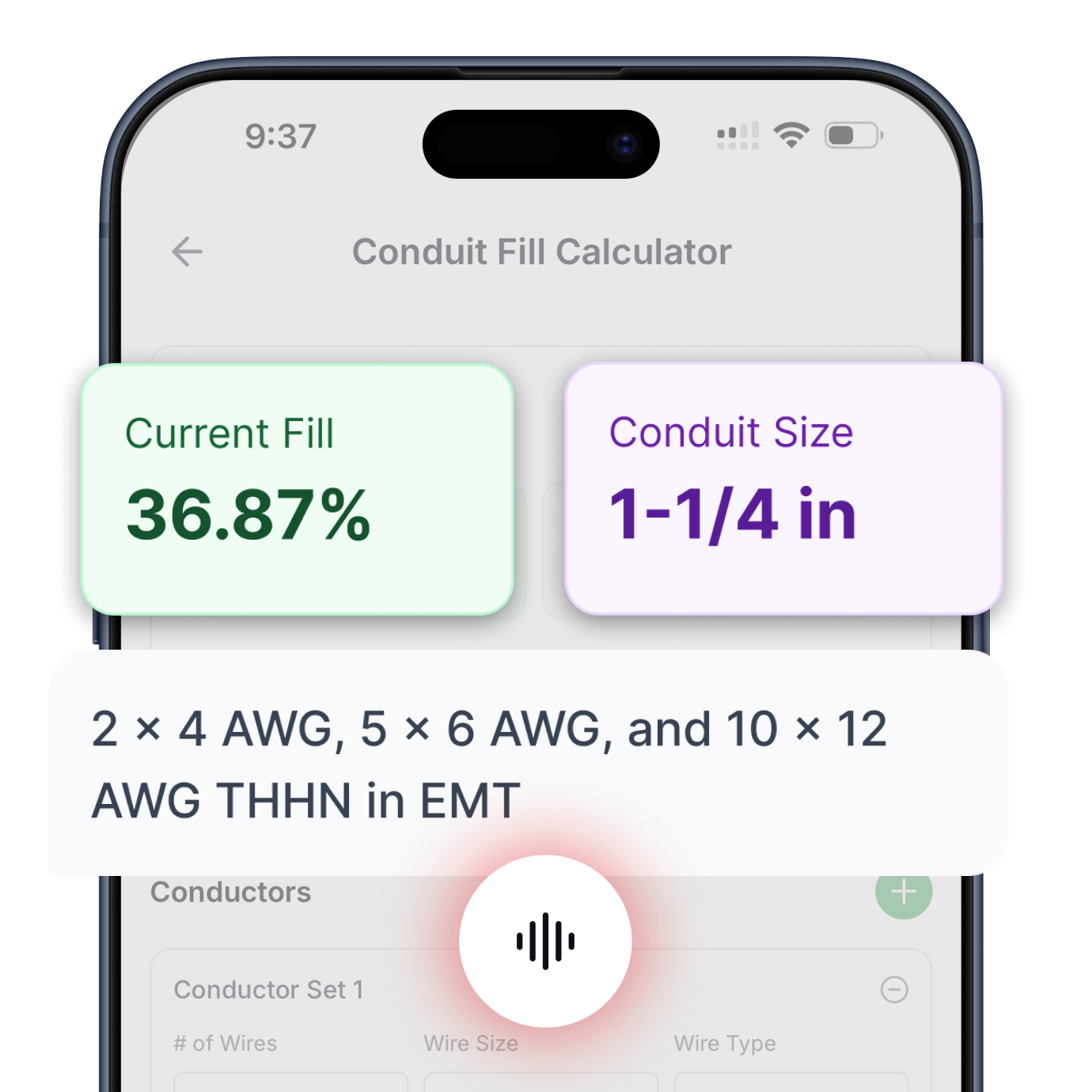
Enter the conductor details and select a conduit type to calculate fill percentage and required conduit size.
Select Phase System to See Voltage
Fill in the required inputs below to instantly generate protection size, conductor size, EGC size, raceway size and maximum circuit length.
No items added
No items added
No items added
No items added
No items added
No items added
No items added
Enter the square footage of the building to calculate the required electrical service size based on building load.
Fill in the required inputs below to instantly generate protection size, conductor size, EGC size, raceway size and maximum circuit length.
Select Phase System to See Voltage
Fill in the required inputs below to instantly generate protection size, conductor size, EGC size, raceway size and maximum circuit length.
Select Primary Voltage to See Secondary Options
Fill in the required inputs below to instantly generate protection, conductor, EGC, bonding jumper, and raceway sizes for both primary and secondary sides.
Select Phase to See Voltage
Fill in the required inputs below to calculate the voltage drop across your circuit based on conductor size, load, and cable length.
Select Phase to See Voltage
Fill in the required inputs below to calculate the maximum circuit distance allowed before voltage drop exceeds your limit.
Select Phase to See Voltage
Fill in the required inputs below to calculate the minimum conductor size needed to stay within your voltage drop limit.
Select Phase System to See Voltage
Select a load input type above
Fill in the required inputs below to instantly generate breaker size, conductor size, EGC size, raceway size and maximum circuit length.
Enter the conductor details and select a conduit type to calculate fill percentage and required conduit size.
Select Phase System to See Voltage
Fill in the required inputs below to instantly generate protection size, conductor size, EGC size, raceway size and maximum circuit length.
No items added
No items added
No items added
No items added
No items added
No items added
No items added
Enter the square footage of the building to calculate the required electrical service size based on building load.
Fill in the required inputs below to instantly generate protection size, conductor size, EGC size, raceway size and maximum circuit length.
Select Phase System to See Voltage
Fill in the required inputs below to instantly generate protection size, conductor size, EGC size, raceway size and maximum circuit length.
Select Primary Voltage to See Secondary Options
Fill in the required inputs below to instantly generate protection, conductor, EGC, bonding jumper, and raceway sizes for both primary and secondary sides.
Select Phase to See Voltage
Fill in the required inputs below to calculate the voltage drop across your circuit based on conductor size, load, and cable length.
Select Phase to See Voltage
Fill in the required inputs below to calculate the maximum circuit distance allowed before voltage drop exceeds your limit.
Select Phase to See Voltage
Fill in the required inputs below to calculate the minimum conductor size needed to stay within your voltage drop limit.
The cooling and heat pump calculator sizes electrical circuits for air conditioning equipment, heat pumps, and refrigeration systems based on manufacturer nameplate information.
These systems present unique electrical challenges because they combine motor loads with motor-compressor loads, requiring special calculation methods outlined in the National Electrical Code (NEC) Article 440. Understanding these requirements ensures reliable operation during peak cooling demands when system failures are most inconvenient.
Air conditioning and heat pump equipment includes outdoor condensing units, air handlers, packaged rooftop units, mini-split systems, and central air conditioning systems. Unlike simple motor loads, these systems contain hermetic refrigerant motor-compressors where the motor operates sealed inside the refrigerant atmosphere.
This construction creates different electrical characteristics than standard motors, with higher locked-rotor current and unique overload protection requirements.
Every air conditioning or heat pump unit carries a nameplate providing essential electrical information determined through manufacturer testing. The two critical values are the Maximum Overcurrent Protection (MOCP) and the Minimum Circuit Ampacity (MCA).
These values account for the compressor motor, condenser fan motor, control circuits, crankcase heaters, and any auxiliary loads that operate simultaneously. Using these nameplate values ensures proper circuit sizing without needing to calculate individual component loads.
The Maximum Overcurrent Protection (MOCP) represents the largest circuit breaker or fuse that can protect the air conditioning equipment. This value comes from extensive manufacturer testing that considers compressor locked-rotor current, running current, additional motor loads, and the thermal characteristics of internal components.
The MOCP ensures the overcurrent device provides adequate protection without nuisance tripping during normal starting and operation.
Air conditioning compressors draw very high current during startup, often five to eight times their running current. This locked-rotor current flows for a brief period while the motor accelerates to operating speed.
Standard circuit breakers must withstand this inrush without tripping, yet still provide protection during fault conditions. The MOCP value balances these competing requirements based on the specific compressor and system design.
The nameplate MOCP includes a fuse or HACR (Heating, Air Conditioning, Refrigeration) designation indicating which type of overcurrent protection was used during testing. If the nameplate specifies "Maximum Fuse 60A," you must use fuses rated 60 amperes or less.
If it specifies "Maximum Circuit Breaker 60A" or "HACR 60A," you can use a circuit breaker. Some nameplates list both fuse and breaker ratings, allowing you to choose either protection type.
The Minimum Circuit Ampacity (MCA) tells you the smallest conductor ampacity that can safely supply the equipment and deliver the electrical energy needed for proper operation. This value already includes all necessary multipliers for continuous operation and accounts for all loads that may operate simultaneously.
Manufacturers calculate MCA using the formula: (compressor RLA × 1.25) + (all other loads). This built-in 125% factor for the compressor accounts for continuous motor operation, so you don't apply additional multipliers when sizing conductors.
Protection sizing for air conditioning equipment uses the nameplate MOCP value directly. Unlike general circuits where you calculate protection from load current, HVAC equipment provides the maximum protection size determined through manufacturer testing and engineering analysis.
This value must not be exceeded to maintain equipment listing, warranty coverage, and safe operation.
The protection device must match the type specified on the nameplate. Circuit breakers and fuses have different time-current characteristics that affect their response to motor starting current.
Circuit breakers use thermal-magnetic elements that heat up over time, allowing brief overcurrents during motor starting. Fuses use a fusible element that melts when overcurrent persists, with dual-element fuses providing time-delay for motor starting.
Standard breaker sizes include 15, 20, 30, 40, 50, 60, 70, 80, 90, 100, and larger values. If the nameplate specifies a maximum protection of 60 amperes, you must use exactly 60 amperes or smaller.
You cannot round up to 70 amperes as you might with some other load types. This strict adherence to nameplate values protects internal components that may not withstand higher fault currents.
Some air conditioning equipment includes internal overload protection that supplements the external overcurrent device. Compressor motor windings often have thermal overloads embedded in the windings that disconnect power when winding temperature exceeds safe limits.
These internal protections work in conjunction with the external circuit breaker or fuse to provide comprehensive protection throughout the system.
Conductor sizing for air conditioning circuits follows NEC Article 440.32, which requires conductor ampacity to be at least equal to the nameplate Minimum Circuit Ampacity (MCA).
The MCA value already includes the 125% factor for continuous motor loads, allowing you to select conductors directly from NEC Table 310.16 without additional multipliers. This simplifies calculations while ensuring adequate conductor capacity.
The ampacity tables provide conductor ratings based on material, size, and temperature. Commercial air conditioning installations typically use the 75°C column in Table 310.16 because commercial equipment terminals and circuit breakers are rated for 75°C connections.
The 75°C rating represents the maximum temperature at the connection point when the conductor carries its rated current in a 30°C ambient temperature.
Residential air conditioning may use either 60°C or 75°C conductor ratings depending on the equipment terminal ratings and circuit breaker specifications. Smaller residential circuit breakers often have terminals rated for both 60°C and 75°C connections, with the specific rating marked on the breaker.
Checking both the air conditioner nameplate and the circuit breaker specifications helps determine which temperature rating governs.
The conductor rating output shows the actual ampacity of the selected conductor from Table 310.16. This value will meet or exceed the nameplate MCA. Having some margin between the MCA and the conductor rating provides benefits for voltage drop and accommodates minor variations in actual operating current.
However, this margin should not be relied upon for adding additional loads to the circuit.
Equipment grounding conductor sizing uses NEC Table 250.122 with the circuit protection size as the lookup value. The equipment grounding conductor provides the critical safety function of creating a low-impedance path for fault current to return to the source, allowing the overcurrent device to clear ground faults quickly.
Air conditioning equipment particularly needs reliable grounding because outdoor units operate in wet environments that increase ground fault risk.
The grounding conductor size increases with larger protection devices because higher-rated overcurrent devices must clear larger fault currents. A circuit protected at 60 amperes requires a 10 AWG copper equipment grounding conductor, while a 100-ampere circuit needs 8 AWG copper.
These sizes ensure the grounding conductor can carry fault current without excessive voltage drop or conductor damage during the fault-clearing time.
Outdoor air conditioning units connect to outdoor disconnect switches that must be grounded properly. The equipment grounding conductor runs from the electrical panel through the disconnect to the air conditioner, maintaining continuous grounding throughout the circuit.
Some installations use metal conduit as the equipment grounding conductor, which is permitted when the conduit provides a continuous low-impedance path.
Aluminum equipment grounding conductors require upsizing compared to copper due to aluminum's higher resistance. Table 250.122 provides separate columns for copper and aluminum grounding conductors.
If you select aluminum for the circuit conductors, verify whether using copper for the equipment grounding conductor might be more practical, as copper's superior conductivity provides better fault protection.
Raceway sizing accounts for the current-carrying conductors plus the equipment grounding conductor, following NEC Chapter 9 requirements. The calculator assumes THHN insulation in EMT conduit, representing standard commercial practice for air conditioning circuits.
Single-phase air conditioners use two current-carrying conductors (hot and neutral or two hots for 240-volt units) plus the equipment grounding conductor.
Conductor cross-sectional areas come from Chapter 9, Table 5, which lists the total area of insulated conductors, including insulation thickness. THHN insulation is relatively thin, minimizing overall conductor diameter and allowing more conductors in a given raceway size.
Each conductor's area is looked up individually based on its size, then all conductor areas are summed to determine total conductor fill.
The minimum raceway size is selected from Chapter 9, Table 4, which lists internal areas for different raceway types and sizes. The total conductor area must not exceed 40% of the raceway's internal area when installing three or more conductors.
This 40% limit provides space for installation, heat dissipation, and protects conductor insulation from damage during pulling.
Outdoor air conditioning installations often use liquid-tight flexible metal conduit for the final connection to the condensing unit. This flexible connection accommodates vibration from compressor operation and allows minor positioning adjustments during installation.
The conduit fill calculation applies equally to flexible and rigid raceways, using the internal dimensions for the specific conduit type selected.
Maximum circuit length calculations use the MCA value as the current input, applying the NEC-recommended voltage drop target of 3% for branch circuits. Air conditioning equipment is particularly sensitive to voltage drop because low voltage affects compressor starting and can prevent the unit from operating properly.
Compressors may fail to start or experience nuisance trips from internal overload protection when the supply voltage drops too low.
Single-phase air conditioners use a voltage drop multiplier of 2, accounting for current flow in both supply and return conductors. The total voltage drop is the sum of the drop in the hot conductor and the drop in the neutral or second hot conductor.
Three-phase equipment uses a multiplier of 1.73 (square root of 3), reflecting the more efficient voltage characteristics of three-phase power distribution.
Conductor resistance varies with material and size, taken from NEC Chapter 9, Table 8 for DC resistance. While air conditioners operate on AC power, using DC resistance provides conservative voltage drop calculations.
AC resistance is slightly higher due to skin effect and other AC phenomena, but the difference is minimal for typical conductor sizes, and the conservative DC values ensure adequate voltage.
Long circuit runs to rooftop air conditioning units or remote outdoor condensers may require conductor sizing beyond the minimum ampacity from MCA. Increasing conductor size by one or two gauges larger than the minimum can significantly improve voltage drop performance, ensuring reliable compressor operation.
The additional conductor cost is often justified by avoiding service calls for low-voltage starting problems.
Single-phase air conditioning equipment commonly operates at 208 or 240 volts in residential and light commercial applications. The 240-volt rating provides better efficiency and starting characteristics than 208 volts, though most equipment is designed to operate on either voltage.
Single-phase 208-volt operation typically occurs in commercial buildings with 208Y/120-volt three-phase services where true 240-volt single-phase is unavailable.
Three-phase air conditioning equipment finds use in larger commercial and industrial installations where higher capacity is needed. Common three-phase voltages include 208, 240, and 480 volts.
Three-phase compressors start more smoothly and operate more efficiently than single-phase units of equivalent capacity, making them preferred for systems above about five tons of cooling capacity.
The voltage selection must match between the electrical supply and the equipment nameplate rating. Air conditioners are designed for specific voltages with typical tolerances of ±10% of rated voltage.
Connecting 208-volt-rated equipment to a 240-volt supply or vice versa can damage the compressor or prevent proper operation. Always verify voltage compatibility before energizing new equipment.
Heat pumps operate on the same voltages as air conditioners and use identical circuit sizing methods. The heating and cooling functions share the same compressor and electrical circuit, so a single calculation covers both modes of operation.
Heat pump auxiliary or emergency heat uses separate circuits sized as resistive heating loads, not included in the main heat pump circuit calculation.
Commercial air conditioning installations typically involve larger equipment with three-phase power and higher voltage. Commercial buildings often have 480Y/277-volt or 208Y/120-volt three-phase services that provide efficient power distribution for multiple air conditioning units.
Circuit sizing uses the 75°C conductor ratings throughout because commercial equipment terminals are rated for 75°C connections.
Residential air conditioning uses single-phase power at 240 volts in most cases, with smaller equipment capacity typically ranging from two to five tons. The outdoor condensing unit and indoor air handler may operate on a single circuit or separate circuits depending on equipment design.
Window air conditioners and small through-wall units operate on 120-volt circuits with different sizing requirements than central systems.
Mini-split systems present unique installation considerations because the outdoor unit and indoor air handler connect through refrigerant lines and control wiring rather than ductwork. The electrical circuit typically serves only the outdoor condensing unit, with low-voltage control wiring running to the indoor units.
Some mini-split systems have multiple indoor units on a single outdoor condenser, with the outdoor unit nameplate MCA and MOCP covering the entire system capacity.
Air conditioning equipment requires a disconnecting means within sight of the equipment per NEC Article 440.14. This disconnect allows service technicians to safely de-energize the unit for maintenance and repairs.
The disconnect must be rated for at least the MCA of the equipment and must accommodate the MOCP rating for overcurrent protection if the disconnect includes fuses.
Outdoor disconnects for air conditioning units typically mount on the building wall near the condensing unit. The disconnect enclosure provides protection from weather and includes a handle that clearly indicates the on/off position.
Non-fusible disconnects only provide a disconnecting means, while fusible disconnects include fuses that serve as the circuit overcurrent protection.
The circuit conductors must be sized based on MCA regardless of whether overcurrent protection is located at the equipment disconnect or back at the electrical panel. If using a fusible disconnect at the equipment, the fuses must not exceed the nameplate MOCP.
Some installations use a circuit breaker at the panel for overcurrent protection plus a non-fusible disconnect at the equipment for local disconnecting means.
Buildings with multiple air conditioning units require separate circuits sized individually for each unit. A branch circuit may serve only one motor-compressor load, preventing interaction between different units and simplifying troubleshooting.
Each circuit calculation uses the specific nameplate values for the equipment it serves, as MCA and MOCP values vary widely between different equipment models and capacities.
Feeder circuits serving multiple air conditioners must account for the combined load with appropriate demand factors. NEC Article 440 allows demand factors when sizing feeders serving multiple motor-compressor loads, recognizing that all units may not operate at peak capacity simultaneously.
However, branch circuits to individual units must always be sized for the full nameplate values without demand reduction.
Electrical panels serving primarily air conditioning loads need careful consideration of available fault current and breaker ratings. Multiple large air conditioning circuits can create a substantial starting surge when multiple units start simultaneously.
Panel bus ratings and main breaker sizing must account for these combined loads while meeting NEC requirements for overcurrent protection coordination.
Heat pumps include auxiliary electric heat strips that supplement the heat pump compressor during extreme cold weather. This auxiliary heat represents a resistive heating load sized separately from the main heat pump circuit.
The auxiliary heat may be controlled to stage on when the heat pump cannot maintain temperature, or may serve as emergency heat when the heat pump malfunctions.
The auxiliary heat circuit requires separate calculation as a resistive heating load, not combined with the heat pump compressor circuit. Heat pump equipment may have nameplate information for both the heat pump circuit and the auxiliary heat circuit, or the auxiliary heat may be listed separately.
Each circuit needs appropriate overcurrent protection, conductors, and grounding sized for its specific load. Modern heat pumps with higher heating seasonal performance factor ratings require less auxiliary heat supplementation, reducing overall electrical demand during cold weather operation.
Some heat pump installations use a single disconnect serving both the heat pump compressor circuit and the auxiliary heat circuit. The disconnect must be rated for the combined load of both circuits and must provide simultaneous disconnection of both circuits.
This arrangement simplifies service work by ensuring complete power removal with a single disconnect operation.
Air conditioning units that fail to start or trip breakers during starting often suffer from low voltage at the equipment. Measuring voltage at the unit while attempting to start helps diagnose voltage drop problems.
The voltage should remain above 90% of rated voltage during starting; lower voltage indicates undersized conductors, excessive circuit length, or loose connections creating resistance.
Compressor locked-rotor current flows briefly during starting, typically for one to three seconds while the motor accelerates. If voltage drops excessively during this period, the compressor may not develop enough starting torque to accelerate properly.
The starting current continues flowing longer than normal, potentially causing thermal overload protection to trip before the compressor reaches running speed.
Nuisance tripping of circuit breakers during normal operation suggests the breaker is undersized or the actual operating current exceeds the nameplate MCA. Measuring actual running current and comparing it to the nameplate-rated load amps helps identify whether the equipment is operating abnormally or the circuit protection is inadequate.
Monitoring the electrical energy consumed during operation can reveal inefficiencies or abnormal load conditions that may indicate developing equipment problems.
Some older circuit breakers develop calibration drift over time, causing them to trip at currents below their rating.
Air conditioning circuits carry full rated load during peak cooling season but remain unused during the heating season in many climates. This seasonal variation affects building electrical demand calculations and can influence decisions about shared neutral conductors or multi-wire branch circuits.
The seasonal nature of cooling loads creates opportunities for demand diversity in service and feeder sizing.
Heat pumps operate year-round but reverse the refrigeration cycle for heating mode. The electrical load remains similar in heating and cooling modes because the compressor operates in both modes.
However, auxiliary electric heat adds significant load during heating mode in cold climates, potentially creating higher electrical demand in winter than summer despite the heat pump operation.
Understanding seasonal load patterns helps with electrical system planning and demand management. Buildings in hot climates may experience peak electrical demand during summer cooling, while cold climate buildings with heat pump auxiliary heat may peak in winter.
Service and feeder sizing must account for the actual peak demand period regardless of when it occurs.
All air conditioning and heat pump calculations reference NEC Article 440 for air-conditioning and refrigerating equipment, along with general requirements from Articles 210, 250, and 310. These code references provide the foundation for safe installations and give inspectors clear documentation of proper circuit sizing.
Manufacturer installation instructions often include additional requirements beyond basic NEC provisions.
Equipment listings through UL or other recognized testing laboratories depend on installation according to manufacturer instructions. Deviating from nameplate values for MOCP and MCA can void the equipment warranty and listing.
Following the nameplate ratings ensures the equipment operates as tested and maintains all safety certifications throughout its service life.
Installation manuals typically specify minimum clearances, maximum circuit length, specific installation methods, and environmental limitations. These requirements address factors beyond basic electrical circuit sizing but affect overall system performance and reliability.
Maintaining complete installation documentation helps with future service work and demonstrates professional installation practices.

Circuit Calculations
Size conductors, breakers, and raceways for any branch circuit or feeder. Includes automatic voltage drop calculations and equipment grounding conductor sizing.
Try Circuit Calculator ->

Load Calculator
Complete dwelling unit load calculations following NEC Article 220. Size service conductors and calculate demand loads for residential installations.
Try Load Calculator ->

Conduit Fill
Determine minimum conduit size based on conductor count and type. Supports all common conductor insulations and raceway types per NEC Chapter 9.
Try Conduit Calculator ->

Transformer Calculator
Complete primary and secondary sizing for single-phase and three-phase transformers. Includes protection, conductors, bonding jumpers, and raceways.
Try Transformer Calculator ->

Motor Calculator
Get proper breaker and fuse sizing for single-phase and three-phase motors from 1/6 HP to 10 HP. Includes conductor sizing and both breaker and fuse options.
Try Motor Calculator ->

Voltage Drop
Three specialized calculators: find minimum conductor size for a given length, calculate maximum circuit length for a conductor size, or determine actual voltage drop percentage.
Try Voltage Drop Calculator ->

Cooling & Heat Pump Calculator
Size circuits for air conditioning or heat pump equipment using nameplate MCA and MOCP values. Handles single-phase and three-phase systems.
Try Cooling & Heat Pump Calculator ->

Resistive Heating Calculator
Calculate circuits for electric heating equipment including baseboard heaters and unit heaters, based on nameplate ratings. Handles single-phase and three-phase systems.
Try Resistive Heating Calculator ->
Get instant, code-compliant answers with voice commands—no typing, no dropdowns, no hassle.