Select Phase System to See Voltage
Select a load input type above
Fill in the required inputs below to instantly generate breaker size, conductor size, EGC size, raceway size and maximum circuit length.
Enter the conductor details and select a conduit type to calculate fill percentage and required conduit size.
Select Phase System to See Voltage
Fill in the required inputs below to instantly generate protection size, conductor size, EGC size, raceway size and maximum circuit length.
No items added
No items added
No items added
No items added
No items added
No items added
No items added
Enter the square footage of the building to calculate the required electrical service size based on building load.
Fill in the required inputs below to instantly generate protection size, conductor size, EGC size, raceway size and maximum circuit length.
Select Phase System to See Voltage
Fill in the required inputs below to instantly generate protection size, conductor size, EGC size, raceway size and maximum circuit length.
Select Primary Voltage to See Secondary Options
Fill in the required inputs below to instantly generate protection, conductor, EGC, bonding jumper, and raceway sizes for both primary and secondary sides.
Select Phase to See Voltage
Fill in the required inputs below to calculate the voltage drop across your circuit based on conductor size, load, and cable length.
Select Phase to See Voltage
Fill in the required inputs below to calculate the maximum circuit distance allowed before voltage drop exceeds your limit.
Select Phase to See Voltage
Fill in the required inputs below to calculate the minimum conductor size needed to stay within your voltage drop limit.
Select Phase System to See Voltage
Select a load input type above
Fill in the required inputs below to instantly generate breaker size, conductor size, EGC size, raceway size and maximum circuit length.
Enter the conductor details and select a conduit type to calculate fill percentage and required conduit size.
Select Phase System to See Voltage
Fill in the required inputs below to instantly generate protection size, conductor size, EGC size, raceway size and maximum circuit length.
No items added
No items added
No items added
No items added
No items added
No items added
No items added
Enter the square footage of the building to calculate the required electrical service size based on building load.
Fill in the required inputs below to instantly generate protection size, conductor size, EGC size, raceway size and maximum circuit length.
Select Phase System to See Voltage
Fill in the required inputs below to instantly generate protection size, conductor size, EGC size, raceway size and maximum circuit length.
Select Primary Voltage to See Secondary Options
Fill in the required inputs below to instantly generate protection, conductor, EGC, bonding jumper, and raceway sizes for both primary and secondary sides.
Select Phase to See Voltage
Fill in the required inputs below to calculate the voltage drop across your circuit based on conductor size, load, and cable length.
Select Phase to See Voltage
Fill in the required inputs below to calculate the maximum circuit distance allowed before voltage drop exceeds your limit.
Select Phase to See Voltage
Fill in the required inputs below to calculate the minimum conductor size needed to stay within your voltage drop limit.
The voltage drop percentage calculator determines the actual voltage loss in electrical conductors based on circuit length, conductor size, load current, and system configuration. This calculation helps verify that electrical circuits deliver adequate voltage to equipment and outlets, ensuring proper operation and efficiency. Understanding voltage drop is essential for quality electrical installations because excessive voltage drop causes equipment malfunction, reduced efficiency, and premature failure even when circuits meet ampacity requirements.
Voltage drop occurs whenever current flows through conductors because all conductors have electrical resistance. This resistance converts some electrical energy into heat, reducing the voltage available at the load compared to the voltage at the source. The amount of voltage drop depends on conductor resistance, current magnitude, and circuit length. Longer circuits, smaller conductors, and higher currents all increase voltage drop.
The NEC doesn't mandate maximum voltage drop limits but provides recommendations in informational notes. NEC 210.19(A) Informational Note No. 4 recommends limiting branch circuit voltage drop to 3% for reasonable efficiency of operation. NEC 215.2(A)(1) Informational Note No. 2 recommends limiting feeder voltage drop to 2.5%, with combined feeder and branch circuit voltage drop not exceeding 5%. These recommendations ensure equipment receives adequate voltage for proper operation.
Voltage drop represents the difference between source voltage and load voltage, expressed as a percentage of source voltage. A 240-volt circuit with 7.2 volts of drop experiences 3% voltage drop (7.2 ÷ 240 × 100 = 3%). This percentage expresses voltage loss in a way that's meaningful across different system voltages, allowing consistent evaluation whether working with 120, 240, 480, or other voltage levels.
Electrical equipment is designed to operate within specific voltage tolerances, typically ±10% of rated voltage. However, operating at the low end of this range reduces efficiency and performance. Motors produce less torque, heating elements generate less heat, and lighting fixtures produce less light when voltage drops below nominal values. The 3-5% voltage drop recommendations keep equipment well within acceptable operating ranges.
Voltage drop affects different equipment types in different ways. Resistive loads like heating elements and incandescent lights simply produce less output proportional to voltage reduction. Motor loads suffer more significantly because torque varies with voltage squared, so 10% voltage reduction creates nearly 20% torque reduction. Electronic equipment may malfunction or shut down when voltage drops below minimum operating thresholds.
The voltage drop calculation accounts for circuit configuration through different multipliers for single-phase and three-phase systems. These multipliers reflect the physical arrangement of conductors and how current flows through the system. Understanding these configurations helps explain why three-phase circuits perform better than single-phase circuits of equivalent conductor size and length.
Single-phase circuits use two conductors for current flow: current travels from the source through one conductor to the load, then returns through the second conductor back to the source. Voltage drop accumulates in both the supply and return conductors, requiring a multiplier of 2 in the voltage drop formula. This multiplier accounts for the total conductor length through which current flows.
The basic voltage drop formula for single-phase circuits is: VD = (2 × L × R × I) ÷ 1000, where VD is voltage drop in volts, L is one-way circuit length in feet, R is conductor resistance in ohms per 1000 feet, and I is load current in amperes. The factor of 2 accounts for current flowing through both supply and return conductors. Dividing by 1000 converts the resistance per 1000 feet to the actual circuit length.
Single-phase circuits operating at 120 volts have only 3.6 volts of allowable drop to meet the 3% recommendation (120 × 0.03). This small voltage margin means 120-volt circuits are particularly susceptible to voltage drop problems, especially for long runs or high-current loads. Many installations use 240 volts instead of 120 volts where possible to double the allowable voltage drop in volts while maintaining the same 3% percentage.
Two-wire DC circuits use the same calculation method as single-phase AC circuits because current flows out through one conductor and returns through the other. The 2× multiplier applies equally to DC installations. Battery-powered systems, solar installations, and DC motor circuits all use this calculation method to ensure adequate voltage reaches the load.
Three-phase circuits distribute current across three phase conductors rather than concentrating it in two conductors as single-phase systems do. This distribution creates more efficient voltage drop characteristics, allowing longer circuit runs or smaller conductors for equivalent voltage performance. The voltage drop formula for three-phase uses a multiplier of 1.73 (the square root of 3) instead of 2.
The three-phase voltage drop formula is: VD = (1.73 × L × R × I) ÷ 1000. The 1.73 multiplier reflects the geometric relationship between line-to-line voltage and line-to-neutral voltage in three-phase systems. This lower multiplier compared to single-phase means three-phase circuits experience less voltage drop for the same conductor size, length, and current.
Three-phase systems provide significant advantages for larger loads and longer circuit runs. A three-phase circuit experiences only 86.5% of the voltage drop of an equivalent single-phase circuit (1.73 ÷ 2 = 0.865). This difference allows using smaller conductors, longer runs, or carrying more current while maintaining acceptable voltage drop. Industrial and commercial facilities use three-phase power extensively to take advantage of these efficiency benefits.
Balanced three-phase loads with equal current in all three phases experience minimal neutral current, so voltage drop calculations use only the phase conductor resistance. Unbalanced three-phase loads or systems with significant neutral current require more complex analysis, but the basic calculation provides reasonable accuracy for most installations.
Conductor resistance is the key variable affecting voltage drop, with values taken from NEC Chapter 9 tables. Table 8 provides DC resistance values for uncoated copper and aluminum conductors at 75°C, listing resistance in ohms per 1000 feet for each conductor size from 18 AWG through 2000 kcmil. These values account for the conductor material and cross-sectional area.
Copper conductors have lower resistance than aluminum conductors of the same size due to copper's superior conductivity. A 12 AWG copper conductor has a resistance of 1.93 ohms per 1000 feet at 75°C, while 12 AWG aluminum has 3.18 ohms per 1000 feet. This difference means aluminum conductors must be sized larger than copper for equivalent voltage drop performance.
Conductor resistance decreases as conductor size increases because larger cross-sectional area provides more metal for current flow. A 10 AWG conductor has approximately 1.2 ohms per 1000 feet, while 8 AWG has about 0.78 ohms per 1000 feet. Each increase in conductor size (decrease in AWG number) significantly reduces resistance and improves voltage drop performance.
Temperature affects conductor resistance, with resistance increasing as temperature rises. The NEC Table 8 values assume 75°C conductor temperature, which is typical for loaded conductors. Conductors operating at higher temperatures have slightly higher resistance, though this difference is usually negligible for voltage drop calculations in typical installations.
AC circuits experience slightly higher resistance than DC circuits due to skin effect and other AC phenomena. As alternating current flows through conductors, the current tends to concentrate near the conductor surface rather than distributing evenly across the cross-section. This skin effect reduces the effective cross-sectional area available for current flow, increasing effective resistance.
NEC Chapter 9, Table 9 provides AC resistance values for insulated conductors in steel conduit, accounting for both skin effect and inductive reactance from nearby conductors. These AC resistance values are typically 10-30% higher than DC resistance values for the same conductor size. The difference becomes more pronounced for larger conductor sizes where skin effect is more significant.
For most residential and light commercial voltage drop calculations, using DC resistance from Table 8 provides conservative results that ensure adequate voltage. The slightly lower DC resistance values predict more optimistic voltage drop than will actually occur, building in a safety margin. For large commercial or industrial installations with conductors larger than 1/0 AWG, using AC resistance values from Table 9 provides more accurate predictions.
Power factor affects voltage drop in AC circuits when inductive or capacitive loads create phase shift between voltage and current. The calculator can account for power factor when specified, though a default value of 0.85 represents typical residential and commercial loads. Unity power factor (1.0) applies to purely resistive loads, while lower power factors indicate more reactive loads.
The load current value determines how much voltage drop occurs for a given conductor size and length. Current flows in response to load demand, with higher loads drawing more current and creating proportionally more voltage drop. The voltage drop calculation uses the actual load current expected during circuit operation, not the conductor ampacity or circuit breaker rating.
Continuous loads operating for three hours or more should use their actual operating current in voltage drop calculations. A circuit serving a 20-ampere continuous load experiences voltage drop based on 20 amperes even if the circuit uses conductors rated for 30 amperes (accounting for the 125% continuous load factor). The voltage drop depends on actual current flow, not conductor capacity.
Motor circuits present special voltage drop considerations because starting current greatly exceeds running current. While the voltage drop calculation typically uses running current to verify steady-state performance, starting conditions should be evaluated separately for motors. Excessive voltage drop during starting can prevent motors from accelerating to operating speed, even if running voltage drop is acceptable.
Variable loads that cycle between different current levels should be evaluated at peak current for voltage drop purposes. A circuit serving equipment that alternates between 10 and 30 amperes should be calculated using 30 amperes to ensure adequate voltage during peak load conditions. Evaluating at average current could result in unacceptable voltage drop during peak periods.
Cable run distance in voltage drop calculations refers to the one-way length from source to load, not the total conductor length. For single-phase circuits, the calculation multiplies this one-way distance by 2 to account for current flow in both supply and return conductors. Three-phase calculations use the one-way distance with the 1.73 multiplier accounting for the three-phase configuration.
Measuring circuit length accurately is important for precise voltage drop calculations. Measure along the actual conductor path including vertical runs, horizontal runs, and any offsets or detours around obstacles. The conductor length exceeds straight-line distance between source and load by 20-40% in typical installations due to routing through conduit and around structural elements.
Voltage drop increases linearly with circuit length, making long runs particularly susceptible to voltage drop problems. Doubling the circuit length doubles the voltage drop for the same conductor size and current. This linear relationship means even small reductions in circuit length can provide meaningful voltage drop improvements when working with long runs.
Circuits routed through unconditioned spaces may experience temperature variations affecting conductor resistance. While standard calculations assume 75°C conductor temperature, conductors in cold environments have lower resistance and better voltage drop performance. Conversely, conductors in hot attics or other high-temperature locations have higher resistance and worse voltage drop performance than calculations predict.
System voltage directly affects voltage drop percentage calculations. The same voltage drop in volts represents different percentages at different system voltages. A circuit with 7.2 volts of drop represents 6% at 120 volts but only 3% at 240 volts. This relationship makes higher voltage systems inherently more resistant to voltage drop problems.
Common residential voltages include 120 volts for lighting and general receptacles and 240 volts for large appliances, electric heating, and air conditioning. Using 240 volts instead of 120 volts where possible allows twice the voltage drop in volts while maintaining the same percentage, effectively allowing longer runs or smaller conductors.
Commercial and industrial facilities use higher voltages including 208, 240, 277, and 480 volts for various applications. Three-phase 480-volt systems are common for large motor loads and distribution feeders because the higher voltage dramatically reduces current requirements and improves voltage drop performance. A given load at 480 volts draws half the current it would at 240 volts, cutting voltage drop to roughly one-quarter for the same conductor size.
Voltage drop calculations should use the nominal system voltage rather than measured voltage at the source. Even if measured voltage is 122 volts, use 120 volts in calculations. This approach provides conservative results because actual voltage may vary, and using nominal voltage ensures calculations remain valid across typical voltage variations.
Copper and aluminum represent the two common conductor materials, with significantly different resistance characteristics. Copper's lower resistance means copper conductors can be smaller than aluminum for equivalent voltage drop performance. However, aluminum costs less and weighs less than copper, making it economical for large conductor sizes and long runs despite requiring larger wire sizes.
The resistance difference between copper and aluminum means a direct size-for-size substitution doesn't work when changing materials. An installation using 8 AWG copper would need approximately 6 AWG aluminum to achieve similar voltage drop performance. The two-size increase accounts for aluminum's roughly 60% higher resistance compared to copper of the same physical size.
Aluminum conductors require special termination methods using anti-oxidant compound and connectors rated for aluminum. Improper aluminum terminations can develop high-resistance connections over time, creating additional voltage drop and potential fire hazards. When selecting aluminum for cost savings, ensure all terminations follow manufacturer requirements and use appropriate materials.
Some jurisdictions restrict or prohibit aluminum conductors for certain applications based on historical problems with improper installations. Modern aluminum conductors and proper installation methods provide safe, reliable service, but local code requirements may limit where aluminum can be used. Always verify local code acceptance of aluminum before designing systems using aluminum conductors.
The calculated voltage drop percentage should be compared to NEC recommendations: 3% maximum for branch circuits and 2.5% for feeders, with combined branch circuit and feeder drop not exceeding 5%. Results within these limits indicate the circuit provides adequate voltage for equipment operation. Results exceeding recommendations suggest the need for larger conductors or circuit modifications.
Voltage drop below 2% is generally excellent and provides significant margin for variations in load, temperature, and voltage supply. This margin helps accommodate inaccuracies in measuring circuit length, variations in actual resistance, and potential future load increases. When calculated voltage drop is very low, the conductor size might be larger than necessary from a voltage drop perspective, though ampacity requirements may still dictate that size.
Voltage drop between 2% and 3% meets NEC recommendations for branch circuits and provides good performance for most equipment. This range balances conductor cost against voltage performance, using conductors sized appropriately for the circuit length and load without excessive oversizing. Equipment operates reliably in this voltage range with minimal efficiency loss.
Voltage drop between 3% and 5% exceeds branch circuit recommendations but may be acceptable for feeder circuits. Evaluate whether the circuit serves critical equipment requiring close voltage regulation, or non-critical loads that can tolerate some voltage variation. If the circuit is a feeder, ensure branch circuits supplied from that feeder maintain their own voltage drop within limits so combined drop doesn't exceed 5%.
When calculated voltage drop exceeds recommendations, several solutions can bring performance within acceptable limits. Increasing conductor size is the most straightforward approach, with each wire size increase reducing resistance by approximately 20-25%. Moving from 12 AWG to 10 AWG or from 10 AWG to 8 AWG significantly improves voltage drop performance.
Reducing circuit length by relocating equipment closer to the power source or installing sub-panels nearer to loads can dramatically reduce voltage drop. Halving the circuit length cuts voltage drop in half. For new construction, strategic placement of electrical panels near major load centers minimizes circuit lengths and voltage drop throughout the facility.
Increasing system voltage where possible provides major voltage drop improvements. Converting from 120-volt to 240-volt operation doubles the allowable voltage drop in volts while maintaining the same percentage. For motor loads and other equipment available in multiple voltage ratings, using higher voltage ratings improves voltage drop performance and reduces conductor size requirements.
Reducing load current through efficiency improvements or load management reduces voltage drop proportionally. Using high-efficiency motors, LED lighting, or other low-current equipment decreases the current flowing through conductors and reduces voltage drop. Load management systems that prevent multiple high-current loads from operating simultaneously can reduce peak current and improve voltage drop during critical operation periods.
When evaluating complete electrical distribution systems, consider the cumulative voltage drop from service entrance through feeders to branch circuits and finally to loads. The NEC recommends combined feeder and branch circuit voltage drop not exceed 5%, requiring careful coordination of both feeder and branch circuit design.
A feeder with 2% voltage drop feeding branch circuits with 2.5% voltage drop creates 4.5% combined drop, meeting the 5% recommendation. However, a feeder with 3% drop only allows 2% for branch circuits to stay within the 5% combined limit. This interaction requires considering the complete distribution system rather than designing feeders and branch circuits independently.
Voltage drop calculations should work backward from the load to the source, evaluating each circuit segment and summing the drops. Start with the branch circuit serving the load, calculate its voltage drop, then move to the feeder serving that panel and calculate its voltage drop. The sum represents the total voltage drop from service to load.
In complex facilities with multiple distribution levels including main service, distribution feeders, sub-feeders, and branch circuits, managing total voltage drop requires systematic design. Each level must maintain its voltage drop within limits that allow downstream circuits to also meet their requirements while keeping total drop within 5%.
Ambient temperature affects conductor resistance and therefore voltage drop. Conductors in hot environments have higher resistance than conductors in cool environments. The standard NEC resistance tables assume 75°C conductor temperature, which represents loaded conductors in typical ambient conditions. Actual resistance varies with temperature at approximately 0.4% per degree Celsius for copper.
Conductors in unconditioned attic spaces may reach 50-60°C ambient temperature during summer, increasing conductor temperature and resistance above table values. This temperature increase creates more voltage drop than calculations predict. Conversely, conductors in conditioned spaces or underground installations may operate cooler than table assumptions, experiencing slightly less voltage drop than calculated.
Solar radiation on outdoor conduits creates additional heating beyond ambient temperature. Black conduit in direct sunlight can reach temperatures 20-30°C above ambient, significantly increasing conductor temperature and resistance. This effect is particularly important for service entrances and outdoor circuits where conduit is exposed to direct sun for many hours daily.
For critical installations or extreme temperature environments, consider using temperature-corrected resistance values rather than standard table values. Multiply the table resistance by [1 + 0.004 × (actual temp °C - 75°C)] to adjust for temperature variations. This refinement provides more accurate voltage drop predictions for conductors operating at temperatures significantly different from 75°C.
Voltage drop can be measured in existing installations by recording voltage at both the source and load while the circuit operates under load. The difference between source voltage and load voltage equals the actual voltage drop. Comparing measured drop to calculated values verifies whether the installation performs as designed.
Measure source voltage at the circuit breaker terminals or panel bus where the circuit originates, with the circuit loaded. Measure load voltage at the equipment terminals or outlet where load connects. Both measurements should occur simultaneously with the load operating to capture actual voltage drop under operating conditions. The voltage difference between these points represents voltage drop in the circuit conductors.
Voltage drop measurements higher than calculated values indicate problems such as undersized conductors, excessive circuit length, loose connections creating additional resistance, or higher actual current than design assumed. Investigate each possibility to identify the cause. Loose connections particularly create localized high resistance that appears as additional voltage drop.
Thermal imaging of energized circuits under load can reveal hot spots indicating high-resistance connections contributing to voltage drop. Connections operating significantly hotter than adjacent conductors suggest resistance problems. Infrared inspection during peak load conditions helps identify voltage drop problems before they cause equipment failures.
Power factor correction in facilities with large motor loads or other reactive equipment can reduce current and improve voltage drop. Installing capacitors to correct power factor reduces the current drawn from the utility, decreasing voltage drop in service and feeder conductors. While this doesn't help branch circuit voltage drop, it improves overall system voltage performance.
Harmonic currents from electronic loads create additional conductor heating and effective resistance beyond what standard calculations predict. Variable frequency drives, electronic ballasts, computer power supplies, and other nonlinear loads generate harmonics that can increase neutral current and voltage drop. Facilities with substantial electronic loads may need oversized neutrals and should use AC resistance values for voltage drop calculations.
Voltage regulation equipment including automatic voltage regulators or tap-changing transformers can compensate for voltage drop in distribution systems. These devices adjust output voltage to maintain constant load voltage despite variations in source voltage or circuit voltage drop. While voltage regulation doesn't eliminate voltage drop, it prevents drop from affecting equipment operation.
Distributed generation from solar panels or other sources affects voltage drop in unexpected ways. During periods when solar generation exceeds local load, current flows backward through conductors from generation to grid connection. This reverse current flow can create voltage rise rather than voltage drop. Utility interconnection studies evaluate these effects to ensure proper operation.
Voltage drop calculations should be documented for permit applications and to demonstrate professional design practices. Record the conductor size, material, circuit length, load current, system voltage, and calculated voltage drop percentage. This documentation helps inspectors verify code compliance and provides reference for future modifications.
While the NEC doesn't mandate voltage drop limits, some local jurisdictions adopt mandatory maximum voltage drop requirements as amendments to the NEC. Always verify local code requirements regarding voltage drop limits. Some jurisdictions require 3% maximum for all circuits, while others follow the NEC informational note recommendations.
Engineer specifications for commercial and industrial projects often specify maximum voltage drop limits more stringent than NEC recommendations. Design specifications may limit branch circuits to 2% and feeders to 3% for combined 5% maximum. Follow project specifications even when they exceed code requirements, as these specifications reflect project quality standards.
Voltage drop affects energy efficiency and operating costs over the life of the installation. Excessive voltage drop wastes energy as heat in conductors rather than delivering it to loads. While larger conductors cost more initially, reduced energy waste and improved equipment performance can provide lifecycle cost savings. Economic analysis balancing initial cost against operating cost helps optimize conductor sizing decisions.

Circuit Calculations
Size conductors, breakers, and raceways for any branch circuit or feeder. Includes automatic voltage drop calculations and equipment grounding conductor sizing.
Try Circuit Calculator ->

Load Calculator
Complete dwelling unit load calculations following NEC Article 220. Size service conductors and calculate demand loads for residential installations.
Try Load Calculator ->

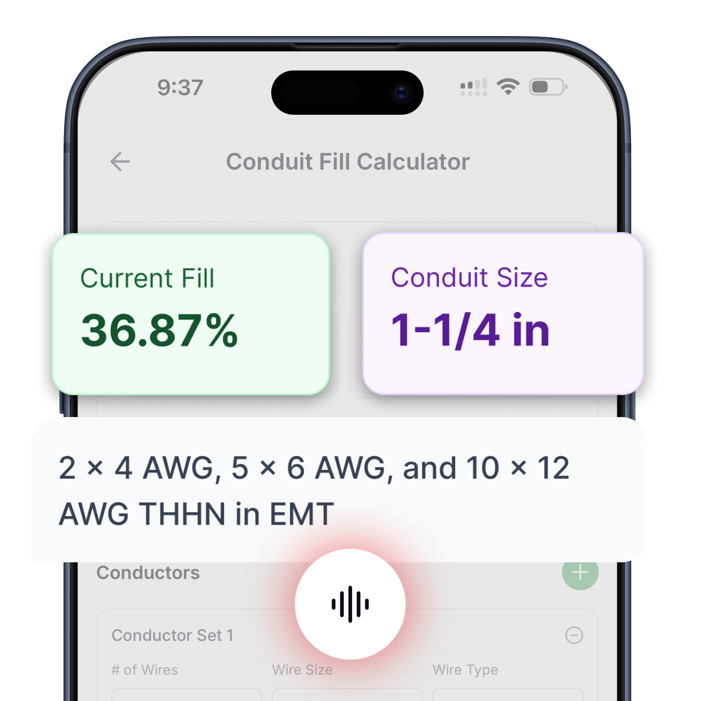
Conduit Fill
Determine minimum conduit size based on conductor count and type. Supports all common conductor insulations and raceway types per NEC Chapter 9.
Try Conduit Calculator ->

Transformer Calculator
Complete primary and secondary sizing for single-phase and three-phase transformers. Includes protection, conductors, bonding jumpers, and raceways.
Try Transformer Calculator ->

Motor Calculator
Get proper breaker and fuse sizing for single-phase and three-phase motors from 1/6 HP to 10 HP. Includes conductor sizing and both breaker and fuse options.
Try Motor Calculator ->

Voltage Drop
Three specialized calculators: find minimum conductor size for a given length, calculate maximum circuit length for a conductor size, or determine actual voltage drop percentage.
Try Voltage Drop Calculator ->

Cooling & Heat Pump Calculator
Size circuits for air conditioning or heat pump equipment using nameplate MCA and MOCP values. Handles single-phase and three-phase systems.
Try Cooling & Heat Pump Calculator ->

Resistive Heating Calculator
Calculate circuits for electric heating equipment including baseboard heaters and unit heaters, based on nameplate ratings. Handles single-phase and three-phase systems.
Try Resistive Heating Calculator ->
Get instant, code-compliant answers with voice commands—no typing, no dropdowns, no hassle.