Select Phase System to See Voltage
Select a load input type above
Fill in the required inputs below to instantly generate breaker size, conductor size, EGC size, raceway size and maximum circuit length.
Enter the conductor details and select a conduit type to calculate fill percentage and required conduit size.
Select Phase System to See Voltage
Fill in the required inputs below to instantly generate protection size, conductor size, EGC size, raceway size and maximum circuit length.
No items added
No items added
No items added
No items added
No items added
No items added
No items added
Enter the square footage of the building to calculate the required electrical service size based on building load.
Fill in the required inputs below to instantly generate protection size, conductor size, EGC size, raceway size and maximum circuit length.
Select Phase System to See Voltage
Fill in the required inputs below to instantly generate protection size, conductor size, EGC size, raceway size and maximum circuit length.
Select Primary Voltage to See Secondary Options
Fill in the required inputs below to instantly generate protection, conductor, EGC, bonding jumper, and raceway sizes for both primary and secondary sides.
Select Phase to See Voltage
Fill in the required inputs below to calculate the voltage drop across your circuit based on conductor size, load, and cable length.
Select Phase to See Voltage
Fill in the required inputs below to calculate the maximum circuit distance allowed before voltage drop exceeds your limit.
Select Phase to See Voltage
Fill in the required inputs below to calculate the minimum conductor size needed to stay within your voltage drop limit.
Select Phase System to See Voltage
Select a load input type above
Fill in the required inputs below to instantly generate breaker size, conductor size, EGC size, raceway size and maximum circuit length.
Enter the conductor details and select a conduit type to calculate fill percentage and required conduit size.
Select Phase System to See Voltage
Fill in the required inputs below to instantly generate protection size, conductor size, EGC size, raceway size and maximum circuit length.
No items added
No items added
No items added
No items added
No items added
No items added
No items added
Enter the square footage of the building to calculate the required electrical service size based on building load.
Fill in the required inputs below to instantly generate protection size, conductor size, EGC size, raceway size and maximum circuit length.
Select Phase System to See Voltage
Fill in the required inputs below to instantly generate protection size, conductor size, EGC size, raceway size and maximum circuit length.
Select Primary Voltage to See Secondary Options
Fill in the required inputs below to instantly generate protection, conductor, EGC, bonding jumper, and raceway sizes for both primary and secondary sides.
Select Phase to See Voltage
Fill in the required inputs below to calculate the voltage drop across your circuit based on conductor size, load, and cable length.
Select Phase to See Voltage
Fill in the required inputs below to calculate the maximum circuit distance allowed before voltage drop exceeds your limit.
Select Phase to See Voltage
Fill in the required inputs below to calculate the minimum conductor size needed to stay within your voltage drop limit.
The transformer calculator determines all electrical requirements for transformer installations based on transformer capacity, voltage ratings, and system configuration. Transformers convert electrical energy from one voltage level to another through electromagnetic induction, serving as critical components in electrical distribution systems. Proper sizing of transformer circuits ensures safe operation, adequate protection, and compliance with NEC Article 450 requirements.
Transformers operate by creating a changing magnetic field in the primary winding that induces voltage in the secondary winding. The voltage transformation ratio depends on the turns ratio between primary and secondary windings, while power capacity remains essentially constant minus small losses. A 50 kVA transformer delivers 50 kVA at either the primary or secondary side, though the voltage and current differ between these connections.
The calculator handles both directions of input: you can specify transformer kVA directly if known, or provide secondary amperage if sizing a transformer for a specific load. Either input method calculates the same transformer requirements because kVA and amperage are mathematically related through voltage. This flexibility accommodates different design scenarios whether selecting a transformer for existing loads or analyzing an installed transformer's circuit requirements.
Transformer capacity is rated in kilovolt-amperes (kVA), which represents the apparent power the transformer can safely handle continuously. A 75 kVA transformer can supply 75,000 volt-amperes at either primary or secondary voltage, though the current differs based on voltage level. The kVA rating accounts for transformer winding capacity, core losses, and thermal limitations under continuous operation.
Standard transformer sizes follow specific increments: 3, 6, 9, 15, 30, 45, 75, 112.5, 150, 225, 300, 500, 750, and 1000 kVA for smaller distribution transformers. Larger power transformers come in increments of 1000, 1500, 2000, 2500 kVA and beyond. Using standard sizes ensures availability from multiple manufacturers and allows proper application of NEC tables and protection requirements.
Single-phase transformers typically range from 3 kVA to 167 kVA for building distribution, serving lighting and receptacle loads, small motor loads, and residential or light commercial facilities. Three-phase transformers range from 15 kVA up to thousands of kVA, serving industrial facilities, commercial buildings, and heavy equipment requiring three-phase power. The phase configuration significantly affects current calculation and circuit sizing.
Transformer efficiency typically exceeds 95% for distribution transformers, meaning losses are relatively small compared to rated capacity. These losses include core losses from magnetizing the core and copper losses from current flowing through windings. While efficiency affects operating cost and transformer temperature rise, the kVA rating already accounts for losses in determining safe continuous capacity.
Primary current is calculated from transformer kVA and primary voltage using the relationship: Current = (kVA × 1000) ÷ (Voltage × Phase Factor). The phase factor equals 1 for single-phase transformers and 1.73 (square root of 3) for three-phase transformers. This calculation determines the current flowing in primary conductors when the transformer operates at full rated load.
A 45 kVA single-phase transformer with 240-volt primary operates at: Primary Current = (45 × 1000) ÷ (240 × 1) = 187.5 amperes at full load. This current flows through primary conductors and determines conductor sizing, protection rating, and raceway requirements. The primary current calculation uses the actual primary voltage, not secondary voltage.
Secondary current uses the same formula with secondary voltage: Current = (kVA × 1000) ÷ (Voltage × Phase Factor). The same 45 kVA transformer with 120/240-volt secondary operates at: Secondary Current = (45 × 1000) ÷ (240 × 1) = 187.5 amperes. In this example, primary and secondary currents are equal because voltages are equal, though this isn't always the case.
Three-phase transformers use the 1.73 multiplier in current calculations, reflecting the three-phase power relationship. A 75 kVA three-phase transformer with 480-volt primary operates at: Primary Current = (75 × 1000) ÷ (480 × 1.73) = 90.4 amperes. The three-phase configuration distributes current across three conductors rather than two, reducing current per conductor for a given kVA capacity.
Primary overcurrent protection for transformers follows NEC Article 450.3, which provides specific protection requirements based on transformer primary voltage and whether secondary protection is provided. The protection ensures transformer primary windings don't overheat during overload or fault conditions while allowing normal inrush current during transformer energization.
Transformers experience significant inrush current when first energized as the magnetic core saturates. This inrush can reach 8 to 12 times rated current for several cycles before settling to normal magnetizing current. Overcurrent protection must allow this brief inrush without nuisance tripping while still providing protection against sustained overloads and faults.
For transformers with primary voltage 1000 volts or less and secondary protection provided, NEC Table 450.3(A) allows primary protection up to 250% of primary current when primary current is 9 amperes or more. If primary current is less than 9 amperes, protection can be up to 167% of primary current. If primary current is less than 2 amperes, protection can reach up to 300% of primary current.
However, the calculator uses 125% to determine a more practical primary protection size, then rounds to the next standard overcurrent device rating. A transformer with 100 amperes primary current allows protection up to 125% × 100A = 125 amperes. If this calculated value doesn't correspond to a standard protection size, NEC 450.3(A) allows using the next higher standard rating, though this exception has limits to prevent excessive oversizing. Technically the NEC allows for a higher rating of OCPD but it results in higher costs for the electrician as you need to upsize conductors.
Primary conductors must be sized at 125% of transformer primary full-load current per NEC Article 450.3. This requirement accounts for continuous transformer operation and provides thermal margin for conductors. Unlike other continuous loads where the 125% factor applies to protection sizing, transformer circuits apply this factor to conductor ampacity requirements.
The required primary conductor ampacity equals primary current × 1.25. A transformer with 80 amperes primary current requires conductors rated for at least 100 amperes (80 × 1.25). This ampacity becomes the lookup value in NEC Table 310.16 to select actual conductor size based on conductor material and temperature rating.
Commercial and industrial transformer installations typically use the 75°C column in Table 310.16 for conductor selection because equipment terminals are rated for 75°C connections. The selected conductor must have ampacity equal to or greater than the required ampacity. If 100 amperes is required, select the smallest conductor with at least 100 amperes rating in the appropriate temperature column.
The conductor rating output shows the actual ampacity of the selected conductor from Table 310.16. This value will exceed the required ampacity, providing margin for ambient temperature variations and voltage drop. However, this margin is not for adding additional loads, as transformer primary circuits should serve only the transformer and associated equipment.
Secondary overcurrent protection follows similar rules as primary protection but often uses tighter protection limits. NEC Table 450.3(A) allows secondary protection up to 125% of secondary current when secondary current is 9 amperes or more. For secondary current less than 9 amperes, protection can reach 167% of secondary current. These percentages are more restrictive than primary protection because secondary circuits directly serve loads.
The tighter secondary protection limits reflect the need to protect secondary conductors and downstream equipment more closely. Secondary circuits typically connect to panelboards, motor control centers, or other distribution equipment serving multiple branch circuits and loads. Closer protection prevents overload conditions from damaging these downstream components.
When transformers provide secondary protection meeting these requirements, primary protection can use the higher percentages mentioned earlier. This coordination between primary and secondary protection ensures comprehensive protection while accommodating transformer characteristics. If secondary protection is omitted or doesn't meet requirements, primary protection must use more restrictive values.
The calculator determines maximum secondary protection size using the 125% factor for secondary current 9 amperes or more, then rounds to the next standard overcurrent device rating. A transformer with 200 amperes secondary current allows protection up to 250 amperes (200 × 1.25). Standard breaker sizes would typically use a 250-ampere device for this application.
Secondary conductors are sized at 125% of transformer secondary full-load current, matching the requirement for primary conductors. This 125% factor accounts for continuous transformer operation and ensures conductors don't overheat during extended full-load operation. The factor provides thermal margin for conductors supplying transformer secondary loads.
Required secondary conductor ampacity equals secondary current × 1.25. A transformer with 150 amperes secondary current requires conductors rated for at least 187.5 amperes (150 × 1.25). Using NEC Table 310.16 with the 75°C column for commercial installations, this would require 3/0 AWG copper conductors rated for 200 amperes.
Secondary conductors must extend from transformer secondary terminals to the secondary overcurrent protection location. If overcurrent protection is located at the transformer, secondary conductors only need to extend to that protection point. If protection is located remotely, conductor sizing becomes more complex following tap conductor rules in NEC 240.21(C).
The conductor rating shows the actual ampacity from Table 310.16 for the selected conductor. This ampacity exceeds the minimum requirement, providing some margin for voltage drop and temperature variations. For long secondary runs, voltage drop calculations may require larger conductors than the minimum ampacity would suggest.
Primary equipment grounding conductor sizing uses NEC Table 250.122 with the primary overcurrent protection device rating as the lookup value. The equipment grounding conductor provides a low-impedance path for fault current on the primary side, allowing overcurrent devices to clear ground faults quickly and safely.
Transformer primary grounding is essential because primary windings and enclosures can become energized during insulation failures or winding-to-ground faults. The equipment grounding conductor connects the transformer enclosure to the grounding electrode system, ensuring fault current has a return path to the source. Proper grounding prevents the transformer enclosure from remaining energized during fault conditions.
The grounding conductor size increases with larger primary protection devices because higher-rated devices must clear larger fault currents. A primary circuit protected at 200 amperes requires a 6 AWG copper equipment grounding conductor, while a 400-ampere primary circuit needs 3 AWG copper. These sizes ensure the grounding conductor can carry fault current without damage during the fault clearing time.
Copper equipment grounding conductors are most common for transformer installations because copper's superior conductivity provides better fault clearing performance. Aluminum grounding conductors are permitted and sized using the aluminum column in Table 250.122, requiring larger wire sizes than copper for equivalent fault current capacity.
The system bonding jumper connects the transformer secondary grounded conductor (neutral) to the equipment grounding system at a separately derived system. This connection establishes the transformer secondary as a new source with its own grounded conductor connection to earth, separate from other grounding points in the electrical system.
Separately derived systems include transformers where secondary windings have no electrical connection to primary windings. Most distribution transformers are separately derived systems requiring bonding jumper installation. The bonding jumper connects the secondary neutral to the transformer enclosure and equipment grounding conductor, creating the reference point for secondary system grounding.
Bonding jumper sizing follows NEC 250.66, using the secondary conductor size to determine minimum bonding jumper size. Unlike equipment grounding conductors that use Table 250.122 based on protection size, bonding jumpers size based on the largest secondary conductor connected to the transformer. This larger sizing reflects the bonding jumper's role in carrying all secondary ground fault current.
A transformer with 3/0 AWG secondary conductors requires a 4 AWG copper bonding jumper per Table 250.66. The table provides minimum bonding jumper sizes based on secondary conductor size, with larger secondary conductors requiring proportionally larger bonding jumpers. Parallel secondary conductors require special bonding jumper sizing calculations accounting for the combined conductor area.
Raceway sizing for transformer circuits follows NEC Chapter 9 requirements, accounting for all conductors in the raceway including current-carrying conductors and equipment grounding conductors. The calculator assumes THHN insulation in EMT conduit, representing standard commercial installation practice. Conductor cross-sectional areas from Chapter 9, Table 5 determine total fill.
Primary raceways contain the number of phase conductors determined by system configuration: two conductors for single-phase or three for three-phase, plus the equipment grounding conductor. Each conductor's area is looked up individually in Table 5 based on conductor size and insulation type. The sum of all conductor areas must not exceed 40% of raceway internal area from Chapter 9, Table 4.
Secondary raceways contain the secondary phase conductors plus the equipment grounding conductor. The bonding jumper typically runs in the same raceway as secondary conductors when raceway provides the path from transformer to secondary disconnect or panelboard. All conductors in the raceway count toward fill calculation regardless of whether they carry load current.
For transformer installations with significant distance between primary source and transformer location, or between transformer and secondary distribution point, raceway sizing becomes important for installation efficiency. Conduit filled near the 40% maximum limit becomes difficult to pull, especially for long runs. Consider using the next size larger raceway than calculated minimum for runs exceeding 50 feet.
Single-phase transformers operate with two primary conductors and typically two or three secondary conductors depending on whether the secondary is configured for 120/240 volt or straight 240-volt output. Single-phase 120/240-volt secondaries provide both 120-volt and 240-volt output through a center-tapped secondary winding, common in residential and light commercial applications.
Three-phase transformers connect primary and secondary windings in delta or wye configurations. Delta-delta, delta-wye, wye-delta, and wye-wye configurations each serve different applications. Delta-wye is common for distribution transformers providing 208Y/120-volt or 480Y/277-volt output from higher primary voltages. The configuration affects voltage relationships but doesn't change basic kVA and current calculations.
Common primary voltages include 480, 240, and 208 volts for commercial transformers, with 13.2 kV and other medium voltages for utility distribution transformers. Secondary voltages include 208Y/120, 480Y/277, and 240/120 volts for building distribution. Voltage selection depends on utility supply availability and equipment voltage requirements.
Three-phase voltage designations using "Y" indicate wye-connected systems with a grounded neutral point. The line-to-neutral voltage equals line-to-line voltage divided by 1.73. A 208Y/120-volt system has 208 volts line-to-line and 120 volts line-to-neutral. Systems designated with a slash like 120/240 indicate single-phase with center-tapped secondary providing two voltages.
The calculator accepts either transformer kVA or secondary amperage as input, providing flexibility for different design scenarios. When specifying a transformer for a known load, entering secondary amperage determines the required transformer kVA. When analyzing an existing transformer, entering nameplate kVA calculates all circuit requirements.
Converting between secondary amperes and transformer kVA uses the formula: kVA = (Secondary Amps × Secondary Voltage × Phase Factor) ÷ 1000. A load drawing 300 amperes at 208 volts three-phase requires: kVA = (300 × 208 × 1.73) ÷ 1000 = 108 kVA. Standard transformer sizes would use either 112.5 kVA or 150 kVA for this load.
Working backward from kVA to determine secondary amperage uses: Secondary Amps = (kVA × 1000) ÷ (Secondary Voltage × Phase Factor). A 75 kVA transformer with 208-volt three-phase secondary provides: Secondary Amps = (75 × 1000) ÷ (208 × 1.73) = 208 amperes maximum continuous load.
Load calculations should include some margin between actual load and transformer capacity to prevent operating transformers continuously at full rated capacity. Operating at 80-90% of rated kVA extends transformer life, accommodates load growth, and prevents overheating during peak demand periods. Slightly oversizing transformers costs little additional money initially but provides operational margin throughout the transformer's service life.
Transformers must be readily accessible per NEC 450.13, allowing inspection, maintenance, and replacement without moving permanent building elements. This accessibility requirement ensures safe operation and facilitates routine maintenance. Transformers in locked rooms or on platforms require adequate access and working clearances.
Working space requirements around transformers follow NEC 110.26, requiring clear space for safe operation and maintenance. Minimum depth of 3 feet (or 3.5 feet for voltages 151-600 volts) must be maintained in front of transformer terminations. Width must allow 30 inches minimum or the width of equipment, whichever is greater. Height extends from floor to 6.5 feet above floor or transformer height, whichever is greater.
Transformers generate heat during operation, requiring adequate ventilation to prevent overheating. Dry-type transformers are available in various temperature ratings including 80°C, 115°C, and 150°C rise above ambient. The temperature rise rating affects required ventilation and clearances from combustible materials. Higher temperature ratings require more clearance or better ventilation.
Environmental considerations affect transformer selection and installation. Indoor transformers in climate-controlled spaces operate in ideal conditions. Outdoor transformers need weatherproof enclosures rated NEMA 3R or better. Transformers in corrosive environments need special enclosures or coatings. Altitude above 3300 feet requires transformer derating or enhanced cooling.
Dry-type transformers use air cooling and contain no liquid insulation, making them suitable for indoor installations in occupied buildings. These transformers use solid insulation materials and rely on convection or forced air cooling. Dry-type transformers are safer for building installations because they eliminate fire risk from insulating fluids.
Liquid-filled transformers use oil or other dielectric fluids for insulation and cooling, providing higher efficiency and better overload capability than dry-type transformers. These transformers typically serve outdoor installations or dedicated transformer vaults because fire codes restrict liquid-filled transformers in occupied buildings. The liquid provides superior cooling but requires containment systems for environmental protection.
Isolation transformers have no electrical connection between primary and secondary windings, establishing a separately derived system. Most distribution transformers are isolation transformers. The isolated secondary allows establishing a new grounding reference independent of primary grounding, providing flexibility in system grounding design.
Autotransformers have a common winding serving as both primary and secondary, making them more compact and economical than isolation transformers of equivalent capacity. However, autotransformers don't provide electrical isolation between primary and secondary, limiting their applications where isolation is required for safety or grounding purposes. Buck-boost transformers commonly use autotransformer connections for small voltage adjustments.
Transformer overcurrent protection must coordinate with downstream protective devices to provide selective operation during faults. Primary protection should allow secondary breakers to clear secondary faults without primary protection operating. This selectivity prevents unnecessarily de-energizing the entire transformer when only a single secondary circuit has faulted.
Ground fault protection may be required for transformers depending on system voltage and configuration. NEC 215.10 and 230.95 require ground fault protection for certain systems. The protection detects ground faults and opens the circuit before ground fault current causes damage. Ground fault protection is especially important for systems with high available fault current.
Temperature sensing in larger transformers provides warning of overload or cooling system failure before damage occurs. Many transformers include built-in temperature sensors monitoring winding temperature. These sensors can trigger alarms or automatic shutdown when temperature exceeds safe limits, protecting the transformer from overheating damage.
Transformer protection must account for both thermal and magnetic stress during through-faults. Short circuits on the secondary side create large magnetic forces between primary and secondary windings that can damage the transformer mechanically. Protection must clear faults quickly enough to prevent mechanical damage from these forces.
Transformer sizing often benefits from demand factors when serving multiple loads with usage diversity. Not all connected loads operate simultaneously at maximum capacity, allowing transformer sizing below the sum of connected loads. NEC Article 220 provides demand factors for various load types that can be applied to transformer sizing.
Lighting and receptacle loads use demand factors from Table 220.42 that reduce calculated load for larger installations. General lighting at 3 VA per square foot and small appliance loads combine with demand factors applied in tiers: 100% for first 3000 VA, 35% for 3001-120,000 VA, and 25% above 120,000 VA. These factors recognize diversity in how occupants use lighting and receptacles.
Motor loads benefit from demand factors when multiple motors serve intermittent duty cycles. Industrial facilities with many motors rarely operate all motors simultaneously at full load. Engineering analysis of actual operating patterns allows applying appropriate demand factors, often resulting in transformer sizes 60-80% of the sum of motor full-load ratings.
Future load growth should be considered when sizing transformers to avoid premature replacement. Installing a transformer with 20-30% spare capacity allows for load additions without transformer replacement. The modest additional cost of oversizing during initial installation is far less than replacing an undersized transformer later. However, excessive oversizing can reduce efficiency and increase no-load losses.
Multiple transformers sometimes operate in parallel to serve large loads or provide redundancy. Parallel transformer operation requires matching voltage ratios, impedances, and phase angles between transformers. Mismatched transformers create circulating currents that waste capacity and overheat transformers without serving useful loads.
Impedance matching is critical for proper load sharing between parallel transformers. Transformers with identical impedance share load proportionally to their kVA ratings. A 75 kVA transformer in parallel with a 150 kVA transformer of identical impedance will carry one-third and two-thirds of the total load respectively. Mismatched impedances cause unequal loading potentially overloading one transformer while underutilizing another.
Parallel transformer protection requires special consideration because fault currents can back-feed from one transformer into a fault on another transformer's secondary. This back-feed can prevent protective devices from operating properly. Careful coordination of overcurrent devices and sometimes differential protection ensures proper fault clearing.
Voltage drop in primary feeders to transformers affects primary voltage available at transformer terminals. Excessive primary feeder voltage drop reduces primary voltage below transformer rated voltage, which reduces secondary voltage proportionally. A transformer with 480-volt rated primary receiving only 460 volts due to feeder voltage drop produces proportionally reduced secondary voltage.
Secondary conductors from transformer to distribution panels or loads experience voltage drop based on secondary current and conductor resistance. Calculate secondary voltage drop using the methods from the voltage drop calculator, with secondary current as the load value. Long secondary runs may require conductors larger than the minimum 125% ampacity to maintain adequate voltage at loads.
Combined primary and secondary voltage drop affects final voltage at loads. Total voltage drop includes utility service drop, primary feeders, transformer impedance drop, and secondary conductors. Each component contributes to total voltage reduction from utility source to final loads. Maintaining total drop within 5% requires managing drop at each level.
Transformer impedance creates internal voltage drop proportional to load. A transformer at full load experiences voltage drop equal to its percent impedance rating. A 3% impedance transformer drops 3% of rated voltage at full load. This internal drop adds to conductor voltage drop in calculating total system voltage drop.
Transformer efficiency affects operating cost over the transformer's 20-30 year service life. High-efficiency transformers cost more initially but reduce energy losses and operating costs. Energy-efficient transformers can save thousands of dollars in energy costs over their lifetime, justifying higher purchase prices through lifecycle cost analysis.
No-load losses occur continuously whenever the transformer is energized, regardless of load. These core losses result from magnetizing the core and represent constant energy consumption. Reducing no-load losses provides the greatest energy savings because these losses occur 24 hours daily throughout the transformer's life.
Load losses vary with transformer loading, increasing as the square of load current. A transformer operating at 50% load experiences only 25% of full-load copper losses. Operating transformers at moderate loading (60-80% of capacity) balances efficiency against adequate capacity for load growth and peak demand periods.
Transformer replacement costs include not just equipment purchase but also installation labor, system downtime, and disposal of old equipment. These costs make proper initial sizing important to avoid premature replacement. Slightly oversizing transformers during initial installation costs relatively little but provides operational margin preventing early replacement.
All transformer installations must comply with NEC Article 450 covering transformers and transformer vaults. Article 450 provides requirements for overcurrent protection, grounding, ventilation, accessibility, and guarding. These requirements ensure safe transformer installation and operation throughout the equipment's service life.
Transformers are listed by testing laboratories including UL and tested to applicable standards such as UL 1561 for dry-type transformers. Listed transformers have been evaluated for electrical safety, temperature rise, and construction quality. Installing listed transformers ensures compliance with code requirements and manufacturer specifications.
Manufacturer installation instructions provide specific requirements beyond general NEC provisions. These instructions cover mounting, clearances, termination methods, and environmental limitations. Following manufacturer instructions maintains equipment warranty and listing, ensuring transformers operate as designed throughout their rated life.
Building codes may impose additional requirements for transformer installations including fire resistance ratings for transformer rooms, seismic bracing in earthquake zones, and flood protection in flood-prone areas. Coordinating electrical code requirements with building code provisions ensures complete code compliance for transformer installations.

Circuit Calculations
Size conductors, breakers, and raceways for any branch circuit or feeder. Includes automatic voltage drop calculations and equipment grounding conductor sizing.
Try Circuit Calculator ->

Load Calculator
Complete dwelling unit load calculations following NEC Article 220. Size service conductors and calculate demand loads for residential installations.
Try Load Calculator ->

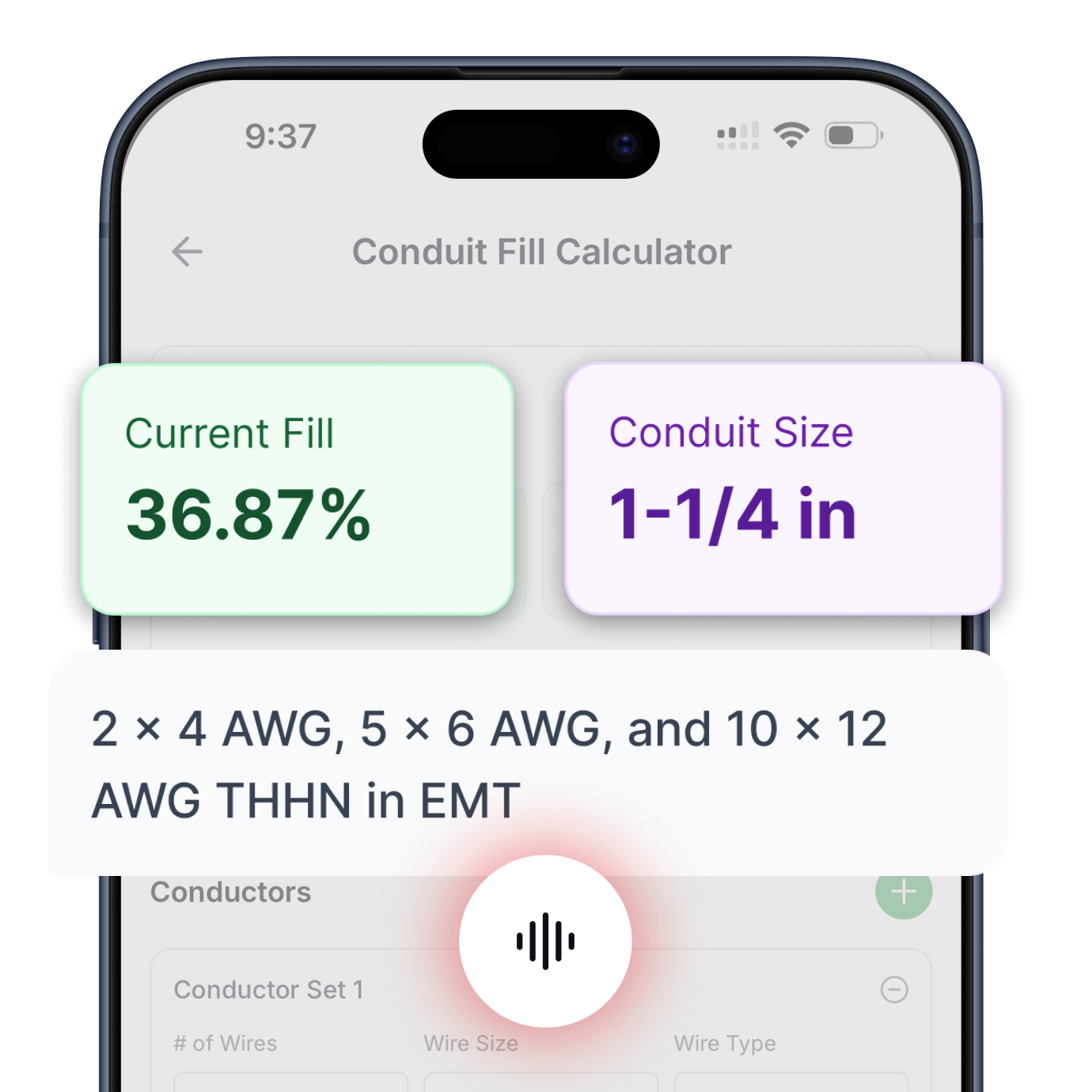
Conduit Fill
Determine minimum conduit size based on conductor count and type. Supports all common conductor insulations and raceway types per NEC Chapter 9.
Try Conduit Calculator ->

Transformer Calculator
Complete primary and secondary sizing for single-phase and three-phase transformers. Includes protection, conductors, bonding jumpers, and raceways.
Try Transformer Calculator ->

Motor Calculator
Get proper breaker and fuse sizing for single-phase and three-phase motors from 1/6 HP to 10 HP. Includes conductor sizing and both breaker and fuse options.
Try Motor Calculator ->

Voltage Drop
Three specialized calculators: find minimum conductor size for a given length, calculate maximum circuit length for a conductor size, or determine actual voltage drop percentage.
Try Voltage Drop Calculator ->

Cooling & Heat Pump Calculator
Size circuits for air conditioning or heat pump equipment using nameplate MCA and MOCP values. Handles single-phase and three-phase systems.
Try Cooling & Heat Pump Calculator ->

Resistive Heating Calculator
Calculate circuits for electric heating equipment including baseboard heaters and unit heaters, based on nameplate ratings. Handles single-phase and three-phase systems.
Try Resistive Heating Calculator ->
Get instant, code-compliant answers with voice commands—no typing, no dropdowns, no hassle.