Select Phase System to See Voltage
Select a load input type above
Fill in the required inputs below to instantly generate breaker size, conductor size, EGC size, raceway size and maximum circuit length.
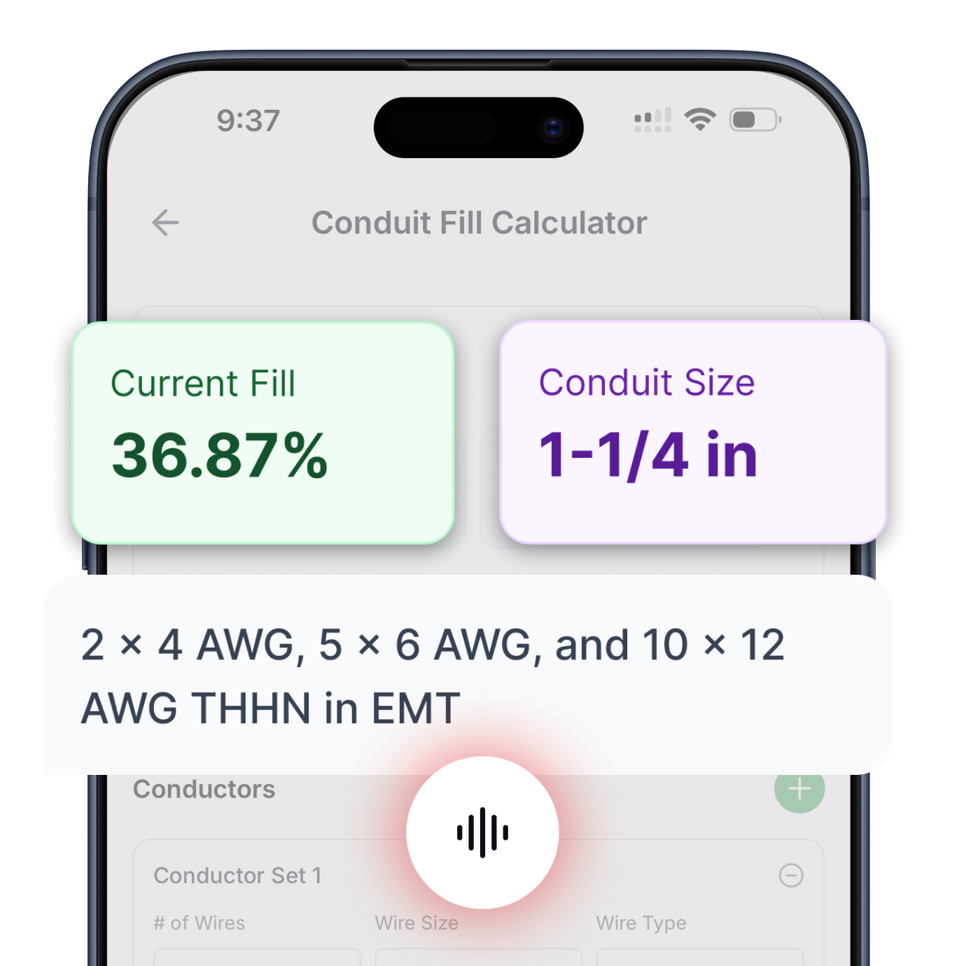
Enter the conductor details and select a conduit type to calculate fill percentage and required conduit size.
Select Phase System to See Voltage
Fill in the required inputs below to instantly generate protection size, conductor size, EGC size, raceway size and maximum circuit length.
No items added
No items added
No items added
No items added
No items added
No items added
No items added
Enter the square footage of the building to calculate the required electrical service size based on building load.
Fill in the required inputs below to instantly generate protection size, conductor size, EGC size, raceway size and maximum circuit length.
Select Phase System to See Voltage
Fill in the required inputs below to instantly generate protection size, conductor size, EGC size, raceway size and maximum circuit length.
Select Primary Voltage to See Secondary Options
Fill in the required inputs below to instantly generate protection, conductor, EGC, bonding jumper, and raceway sizes for both primary and secondary sides.
Select Phase to See Voltage
Fill in the required inputs below to calculate the voltage drop across your circuit based on conductor size, load, and cable length.
Select Phase to See Voltage
Fill in the required inputs below to calculate the maximum circuit distance allowed before voltage drop exceeds your limit.
Select Phase to See Voltage
Fill in the required inputs below to calculate the minimum conductor size needed to stay within your voltage drop limit.
Select Phase System to See Voltage
Select a load input type above
Fill in the required inputs below to instantly generate breaker size, conductor size, EGC size, raceway size and maximum circuit length.
Enter the conductor details and select a conduit type to calculate fill percentage and required conduit size.
Select Phase System to See Voltage
Fill in the required inputs below to instantly generate protection size, conductor size, EGC size, raceway size and maximum circuit length.
No items added
No items added
No items added
No items added
No items added
No items added
No items added
Enter the square footage of the building to calculate the required electrical service size based on building load.
Fill in the required inputs below to instantly generate protection size, conductor size, EGC size, raceway size and maximum circuit length.
Select Phase System to See Voltage
Fill in the required inputs below to instantly generate protection size, conductor size, EGC size, raceway size and maximum circuit length.
Select Primary Voltage to See Secondary Options
Fill in the required inputs below to instantly generate protection, conductor, EGC, bonding jumper, and raceway sizes for both primary and secondary sides.
Select Phase to See Voltage
Fill in the required inputs below to calculate the voltage drop across your circuit based on conductor size, load, and cable length.
Select Phase to See Voltage
Fill in the required inputs below to calculate the maximum circuit distance allowed before voltage drop exceeds your limit.
Select Phase to See Voltage
Fill in the required inputs below to calculate the minimum conductor size needed to stay within your voltage drop limit.
The conduit fill calculator determines the minimum raceway size needed to safely install conductors while meeting NEC Chapter 9 requirements. These requirements exist to prevent conductor damage during installation, allow proper heat dissipation during operation, and ensure conductors can be pulled through raceways without excessive force that could damage the insulation.
Conduit fill limits are not arbitrary percentages but carefully established values based on decades of electrical installation experience and testing. Overfilled conduit makes wire pulling difficult or impossible, increases the risk of insulation damage, and can cause conductors to overheat by restricting air circulation and heat dissipation. The calculator ensures your installation avoids these problems by accurately calculating total conductor area and comparing it to available conduit space.
The calculation process involves three main steps: determining the allowable fill percentage based on conductor count, finding the total cross-sectional area of all conductors, and selecting the minimum conduit size where the allowable fill area exceeds the total conductor area. Each step relies on specific NEC tables that provide standardized values for consistent, code-compliant installations.
The number of conductors in a raceway directly determines the maximum allowable fill percentage. This relationship appears in NEC Chapter 9, Table 1, which establishes different limits based on how many conductors are present. The percentages account for the physical space conductors occupy and the clearance needed for installation and heat dissipation.
When only one conductor runs through a conduit, the maximum fill is 53% of the conduit's internal cross-sectional area. Single-conductor installations are relatively uncommon but occur with large feeder cables where each phase conductor runs in a separate conduit to manage heat dissipation and electromagnetic forces. The higher fill percentage recognizes that a single large conductor is easier to install than multiple smaller ones.
Two-conductor installations have the most restrictive fill limit at 31% of the conduit area. This lower percentage accounts for the geometry of trying to fit two round objects into a circular conduit. Two conductors create more wasted space than either one conductor or three or more conductors, and the tighter packing makes installation more difficult without some additional clearance.
Three or more conductors allow a 40% fill percentage. Most electrical installations fall into this category since typical circuits include at least two current-carrying conductors plus an equipment grounding conductor. The 40% limit provides adequate space for installation while efficiently using available conduit capacity. As the number of conductors increases, they pack more efficiently into the circular conduit cross-section.
Different conduit types and sizes have different internal diameters and cross-sectional areas. NEC Chapter 9, Table 4 lists these dimensions for every combination of conduit type and trade size. The table is essential because the trade size stamped on conduit doesn't represent the actual internal diameter but rather a standardized size designation.
EMT, or Electrical Metallic Tubing, has relatively thin walls and provides more internal space than heavier-wall conduit types of the same trade size. A three-quarter inch EMT has an internal area of 0.213 square inches, while three-quarter inch rigid metal conduit has only 0.220 square inches despite the same trade size designation. These differences matter when calculating conduit fill, especially in installations approaching the maximum allowable fill.
PVC and other nonmetallic conduit types often have different internal dimensions than metallic conduits of the same trade size. Schedule 40 PVC has thicker walls than Schedule 80, giving it more internal area. The calculator uses the specific internal area values from Table 4 for your selected conduit type, ensuring accurate results regardless of which raceway system you're installing.
The conduit's internal area multiplied by the allowable fill percentage from Table 1 gives the maximum usable area for conductors. This usable area represents the total cross-sectional space available for all conductors combined. Any conductor combination that fits within this area will meet code requirements; exceeding it means you need a larger conduit or fewer conductors.
Every insulated conductor has a specific cross-sectional area that includes both the copper or aluminum conductor itself and the surrounding insulation. NEC Chapter 9, Table 5 lists these areas for conductors by wire size and insulation type. The total area varies significantly between insulation types because different insulation materials have different thickness requirements.
THHN insulation is among the thinnest commonly used insulation types, making THHN conductors smaller in overall diameter than other insulation types of the same wire gauge. A 12 AWG THHN conductor has a cross-sectional area of 0.0133 square inches, while a 12 AWG THWN-2 conductor has an area of 0.0133 square inches as well since these insulation types have similar dimensions. However, a 12 AWG RHW-2 conductor has a larger area due to its thicker insulation.
The calculator handles mixed conductor sizes and insulation types by looking up each conductor's area individually from Table 5. If your installation includes different gauge wires or different insulation types, the calculator accounts for these variations. This flexibility matters in real installations where you might run power conductors of one size alongside smaller control wires or equipment grounding conductors.
Equipment grounding conductors must be included in the conductor count and area calculation. The ground wire occupies physical space in the raceway just like current-carrying conductors. Many electricians forget to include the ground wire when estimating conduit fill, which can lead to undersized raceways and difficult installations. The calculator ensures the ground conductor is properly accounted for in the total fill calculation.
Different insulation types serve different applications based on temperature ratings, moisture resistance, and environmental conditions. THHN insulation is rated for 90°C in dry locations and is the most commonly used wire type in commercial and industrial installations. Its thin insulation allows for smaller overall conductor size, making it ideal for conduit installations where space is limited.
THWN and THWN-2 insulation provides moisture resistance, allowing these conductors to be used in wet locations. Many conductors carry a dual rating such as THHN/THWN-2, meaning they meet the requirements for both insulation types. This versatility makes them suitable for virtually any installation environment without needing to stock multiple wire types.
USE and USE-2 insulation is designed for underground installations, with thicker insulation that resists moisture and physical damage from direct burial. RHW and RHW-2 insulation offers heat and moisture resistance for demanding applications. Each insulation type has different dimensions in Table 5, so selecting the correct insulation type ensures accurate conduit fill calculations.
When conductors carry dual ratings like THHN/THWN-2, use the dimensions for THHN since both designations apply to the same physical conductor. The calculator includes common insulation types to match what's actually available from electrical suppliers. Some specialty insulation types like mineral-insulated cable or high-voltage insulation require different calculation methods and aren't included in standard conduit fill calculations.
EMT is the most common raceway in commercial construction because it balances cost, weight, and protection. Its relatively thin walls maximize internal space while still providing mechanical protection for conductors. EMT requires compression or set-screw connectors rather than threaded connections, making installation faster than rigid conduit systems.
Rigid metal conduit and intermediate metal conduit offer superior mechanical protection for exposed installations or areas where physical damage is likely. Their thicker walls result in less internal area than EMT of the same trade size, which means they may require upsizing compared to an EMT installation with the same conductors. The added protection often justifies the cost in industrial settings or outdoor exposed installations.
PVC conduit provides corrosion resistance for underground or corrosive environments. Schedule 40 PVC works for most underground applications, while Schedule 80 provides additional strength for exposed installations or areas subject to physical damage. The calculator includes both schedules because they have different internal dimensions that affect fill calculations.
Flexible metal conduit and liquidtight flexible conduit allow for movement and vibration isolation in motor connections and other dynamic applications. These flexible raceways generally have less internal area than rigid systems of the same trade size due to their corrugated construction. Electrical nonmetallic tubing offers a lightweight, low-cost option for residential installations where it's permitted by local code.
Real electrical installations often involve multiple conductors of different sizes running through the same raceway. Three-phase circuits typically include three current-carrying conductors of the same size plus a smaller equipment grounding conductor. The calculator handles this by adding up the individual areas of each conductor based on its specific size and insulation type.
When neutral conductors are required, they occupy space in the raceway and must be included in the fill calculation. In three-phase four-wire systems, the neutral may be the same size as the phase conductors or may be smaller if reduced neutral sizing is permitted. The calculator allows you to specify each conductor individually to account for these variations.
Control circuits running alongside power conductors present another common scenario. A motor circuit might include three large power conductors plus several smaller control wires for start/stop functions. Each wire, regardless of its function, counts toward the total conductor area and the conductor count for determining the allowable fill percentage.
Spare conductors installed for future use must also be included in the conduit fill calculation. Even though these conductors don't initially carry current, they occupy physical space in the raceway. Proper planning includes these future conductors in the initial calculation to avoid having to install additional raceways later.
The maximum allowable fill percentages in Chapter 9, Table 1 represent absolute limits, not targets. Installations near the maximum fill become increasingly difficult to pull, with higher risk of insulation damage and greater labor cost. Many experienced electricians aim for 30-35% fill rather than the maximum 40% to ease installation and leave room for future conductors.
Long conduit runs magnify the difficulty of pulling conductors at high fill percentages. A thirty-foot run at 38% fill might be manageable, but a three-hundred-foot run at the same fill percentage could prove nearly impossible to pull without exceeding the tensile strength limits of the conductors. For long runs, consider upsizing the conduit even if the calculation shows a smaller size would technically meet code.
Multiple bends in a conduit run also increase pulling difficulty. The NEC limits conduit runs to 360 degrees of total bends between pull points for this reason. When a run includes multiple bends, reducing the fill percentage below the maximum makes pulling significantly easier and reduces installation time.
Wire pulling lubricant helps reduce friction during installation but doesn't change the fill calculation. The lubricant reduces pulling forces but doesn't affect the physical space conductors occupy. Always calculate conduit fill based on the conductor dimensions from Table 5, which already account for the insulation thickness.
The most frequent conduit fill error is forgetting to include the equipment grounding conductor in the count. Since the ground wire doesn't carry load current under normal conditions, people sometimes overlook it when estimating conduit size. This oversight can result in attempting to install more conductors than the raceway can accommodate.
Using the wrong insulation type dimensions creates another common error. If you calculate fill using THHN dimensions but actually install conductors with thicker RHW insulation, the conductors won't fit in the calculated conduit size. Always verify the actual insulation type marked on the conductors before beginning installation.
Confusing conductor count with the number of circuits also causes problems. A single-phase circuit includes two current-carrying conductors plus a ground, totaling three conductors. Some people mistakenly count this as one conductor when determining fill percentage, leading to significant undersizing of the raceway.
Mixing up the conductor gauge and cross-sectional area is another error. A 12 AWG conductor is smaller than a 10 AWG conductor, which confuses people unfamiliar with how wire gauge numbering works. The calculator handles this by using actual cross-sectional area from Table 5 rather than gauge numbers, but understanding the gauge system helps verify results make sense.
Parallel conductors for high-ampacity circuits require special attention to conduit fill. Each set of paralleled conductors must include all phases and the neutral if required. If you're running two sets of 500 kcmil conductors per phase in a three-phase system, you need multiple conduits with each conduit containing a complete set of phase conductors to maintain proper current balance and avoid inductive heating.
Tap conductors that reduce in size along a feeder run need appropriate conduit sizing at each transition point. The conduit near the supply end accommodates the larger feeder conductors, while conduit at the tap location only needs to fit the smaller tap conductors. Calculate each conduit section separately based on the conductors it actually contains.
Communication and data cables have different fill requirements than power conductors and shouldn't be mixed with power wiring in the same raceway except where specifically permitted. When separate raceways are required, calculate each system's conduit fill independently using the appropriate tables for that cable type.
Conduit fill calculations provide documentation needed for electrical inspections. Inspectors may verify conduit sizing on larger installations, particularly where multiple large conductors run through single raceways. Having calculations available that reference specific NEC tables demonstrates code compliance and professional installation practices.
The NEC Annex C provides conduit fill tables for common conductor combinations, offering a quick reference for standard installations. However, these tables only cover specific combinations of conductor size, insulation type, and conduit type. The calculator provides flexibility for any combination, including mixed conductor sizes and less common insulation types not covered in Annex C.
Proper conduit fill ensures long-term installation reliability. Overfilled raceways can cause conductor insulation to degrade over time from heat buildup and mechanical stress. The initial installation might seem successful, but problems emerge years later as insulation breaks down. Following the calculation ensures your installation maintains its integrity throughout its service life.

Circuit Calculations
Size conductors, breakers, and raceways for any branch circuit or feeder. Includes automatic voltage drop calculations and equipment grounding conductor sizing.
Try Circuit Calculator ->

Load Calculator
Complete dwelling unit load calculations following NEC Article 220. Size service conductors and calculate demand loads for residential installations.
Try Load Calculator ->

Conduit Fill
Determine minimum conduit size based on conductor count and type. Supports all common conductor insulations and raceway types per NEC Chapter 9.
Try Conduit Calculator ->

Transformer Calculator
Complete primary and secondary sizing for single-phase and three-phase transformers. Includes protection, conductors, bonding jumpers, and raceways.
Try Transformer Calculator ->

Motor Calculator
Get proper breaker and fuse sizing for single-phase and three-phase motors from 1/6 HP to 10 HP. Includes conductor sizing and both breaker and fuse options.
Try Motor Calculator ->

Voltage Drop
Three specialized calculators: find minimum conductor size for a given length, calculate maximum circuit length for a conductor size, or determine actual voltage drop percentage.
Try Voltage Drop Calculator ->

Cooling & Heat Pump Calculator
Size circuits for air conditioning or heat pump equipment using nameplate MCA and MOCP values. Handles single-phase and three-phase systems.
Try Cooling & Heat Pump Calculator ->

Resistive Heating Calculator
Calculate circuits for electric heating equipment including baseboard heaters and unit heaters, based on nameplate ratings. Handles single-phase and three-phase systems.
Try Resistive Heating Calculator ->
Get instant, code-compliant answers with voice commands—no typing, no dropdowns, no hassle.