June 30, 2026
Dakota Motor Bank Feeder Guide for Red Seal Exam (CEC 2024)
Red Seal Exam Question Guides
June 30, 2026
Red Seal Exam Question Guides
You have a group of motors (a motor bank) that are all connected to a single feeder conductor — and you need to size that conductor correctly so it doesn’t overheat or trip the system when the motors run.
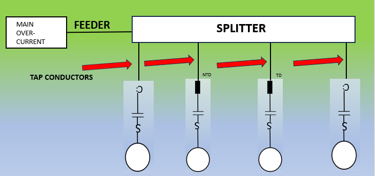
This follows CEC Rule 28-108 which gives us a method to size the feeder conductor based on the types of motor duty (continuous, short-time, or intermittent).
According to Rule 28-108(1)(a):
Take the largest continuous duty motor, multiply its FLA by 125%, then add the FLA of any other continuous duty motors.
Use multipliers from Table 27:
Now add all the calculated values:
Total= 86 + 55 + 51 = 192A
Use CEC Table 2, 75°C column:
Answer: 3/0 AWG copper is your minimum feeder conductor size
Since this feeder conductor doesn’t directly touch any motors, Rule 4-006 (conductor correction/derating) may apply depending on your installation (e.g., ambient temp, bundling, etc.).
Download now to access 2,500+ practice questions and master the Canadian Electrical Code!
